FMS7401LVN14 Fairchild Semiconductor, FMS7401LVN14 Datasheet - Page 44
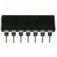
FMS7401LVN14
Manufacturer Part Number
FMS7401LVN14
Description
IC CTRLR POWER DGTL EEPROM 14DIP
Manufacturer
Fairchild Semiconductor
Datasheet
1.FMS7401LVN.pdf
(81 pages)
Specifications of FMS7401LVN14
Applications
Digital Power Controller
Core Processor
8-Bit
Program Memory Type
EEPROM (1 kB)
Ram Size
64 x 8
Number Of I /o
8
Voltage - Supply
2.7 V ~ 3.6 V
Operating Temperature
-40°C ~ 125°C
Mounting Type
Through Hole
Package / Case
14-DIP (0.300", 7.62mm)
Output Current
5 mA
Input Voltage
2.7 V to 3.6 V
Switching Frequency
2 MHz
Operating Temperature Range
- 40 C to + 125 C
Mounting Style
Through Hole
Lead Free Status / RoHS Status
Lead free / RoHS Compliant
Interface
-
Controller Series
-
Lead Free Status / Rohs Status
Lead free / RoHS Compliant
Other names
FMS7401LVN14_NL
FMS7401LVN14_NL
FMS7401LVN14_NL


PRODUCT SPECIFICATION
FMS7401L
9
Multi-input Wakeup Circuit
1
The Multi-input Wakeup (MIW) circuit may be used to wake the device from either Halt or Idle Mode
with an external event,
generate flags for software monitoring and microcontroller hardware interrupts by any one or all I/O ports (G0–G7). The MIW
circuit is configured using the Wakeup Enable (WKEN), Wakeup Edge (WKEDG), Wakeup Pending (WKPND) and
2
T0CNTRL memory mapped registers.
The WKEN, WKEDG and WKPND are 8-bit registers where each bit corresponds to
an I/O port pin (see
Table
21). All four registers are initialized to 0x00 upon a system reset.
The PWMOFF output signal may also be programmed as an input of the G6 port MIW circuit. Interrupts may be triggered if
the PWMOFF/G6 input MIW circuit is enabled and configured to trigger its microcontroller hardware interrupt (EDGEI).
Bit 6 (PWMINT) of the DDELAY register, if set to 1, selects the PWMOFF signal in place of its G6 input to the MIW circuit.
Software must then enable the MIW PWMOFF/G6 circuit by setting the WKEN[6] bit. The WKEDG[6] bit must also be
cleared to select the rising edge transitions on the PWMOFF signal as its WKPND[6] bit trigger. Software may monitor the
WKPND[6] flag or enable the MIW hardware interrupt (EDGEI) to help detect when the PWMOFF signal is triggered. Refer
to the
Programmable Comparator Circuit
sections of the datasheet for addition details.
9.1
MIW Configuration Registers
The Wakeup Enable (WKEN) register individually enables an I/O port’s edge transition to trigger a wakeup/interrupt pending
flag. If the WKEN register bit is 1, the corresponding I/O port’s MIW circuitry (defined by its bit number) is enabled; other-
wise, the port circuitry remains disabled and the pending flag may not be triggered.
The Wakeup Edge (WKEDG) register bits are used to program an enabled I/O port’s pending flag to be triggered from either a
rising-/falling-edge transition. If the WKEDG register bit is 1, a falling-edge transition of the enabled I/O port will trigger the
pending flag. If zero, a rising-edge transition of the enabled I/O port will trigger the pending flag.
The MIW circuit shares a single hardware interrupt (EDGEI) among all pending flags and is enabled by the Wakeup Interrupt
2
enable (WKINTEN) bit of the T0CNTRL register.
The WKINTEN bit enables hardware interrupts for the MIW circuit if set
3
to 1.
The Wakeup Pending (WKPND) register contains the pending flags corresponding to each of the I/O port pins. If a WKPND
register bit is 1, the programmed I/O port edge transition has triggered its pending flag. If zero, the flag is not pending and no
transition has occurred from the last pending reset. A pending flag may only be triggered by enabled I/O ports (if its WKEN
register bit is 1). Once a pending flag is triggered, all flags are logically-ORed together to trigger a WAKEOUT if in Halt/Idle
Mode and/or hardware interrupts (if enabled). If software is to re-enter Halt/Idle Mode, all pending flags must be cleared, oth-
erwise the command is ignored. Since all MIW pending flags share a single hardware interrupt, software must take care with
the handling of the pending flags when more than one pending flag is enabled. As long as a MIW pending flag is set, the hard-
ware interrupt will continue to execute software’s MIW interrupt service routine with highest priority until all pending flags are
4
cleared.
Upon exiting Halt/Idle Mode or before leaving software’s MIW interrupt service routine, the RBIT instruction may be used to
clear a particular pending flag. The RBIT instruction takes two instruction clock cycles to complete its execution. In the first
cycle, all eight register bits are automatically read to obtain their most current value. In the second cycle, the bit to be cleared is
given its new value and all bits are then re-written to the register. Using the RBIT instruction to clear an individual pending flag
causes no potential hazards if only one wakeup I/O port is enabled. However, if more than one I/O port is enabled software may
inadvertently clear a recently triggered pending flag if the trigger happened during the second phase of the RBIT instruction
execution. To avoid this condition, the LD instruction must be used to clear a set pending flag. The MIW circuit is designed
such that software may not trigger a pending flag by writing a 1 to a WKPND register bit, it may only be cleared. The action of
writing a 1 to a WKPND register bit holds the current bit value. The action of writing a 0 to a WKPND register bit clears the bit
value. Therefore, the “LD WKPND, #0F7H” instruction will clear the WKPND[3] while all others bits remain the same.
44
REV. 1.0.3 1/24/05
Related parts for FMS7401LVN14
Image
Part Number
Description
Manufacturer
Datasheet
Request
R

Part Number:
Description:
Digital Power Controller
Manufacturer:
Fairchild Semiconductor
Datasheet:
Part Number:
Description:
Digital Power Controller
Manufacturer:
Fairchild Semiconductor
Datasheet:
Part Number:
Description:
Fairchild Semiconductor [IGBT MODULE]
Manufacturer:
Fairchild Semiconductor
Datasheet:

Part Number:
Description:
Discrete Semiconductor Modules
Manufacturer:
Fairchild Semiconductor
Part Number:
Description:
Discrete Semiconductor Modules
Manufacturer:
Fairchild Semiconductor
Part Number:
Description:
This N-Channel MOSFET is produced using Fairchild Semiconductor’s advanced Power Trench® process
Manufacturer:
Fairchild Semiconductor
Datasheet:
Part Number:
Description:
This N-Channel MOSFET is produced using Fairchild Semiconductor’s advanced Power Trench® process
Manufacturer:
Fairchild Semiconductor
Datasheet:
Part Number:
Description:
This N-Channel MOSFET is produced using Fairchild Semiconductor’s advanced PowerTrench® process
Manufacturer:
Fairchild Semiconductor
Datasheet:
Part Number:
Description:
This N-Channel MOSFET is produced using Fairchild Semiconductor’s advanced PowerTrench® process
Manufacturer:
Fairchild Semiconductor
Datasheet:
Part Number:
Description:
This N-Channel MOSFET is produced using Fairchild Semiconductor’s advanced Power Trench® process
Manufacturer:
Fairchild Semiconductor
Datasheet:
Part Number:
Description:
This N-Channel logic Level MOSFETs are produced using Fairchild Semiconductor‘s advanced Power Trench® process that has been special tailored to minimize the on-state resistance and yet maintain superior switching performance
Manufacturer:
Fairchild Semiconductor
Datasheet:
Part Number:
Description:
This N-Channel MOSFET is produced using Fairchild Semiconductor’s advanced Power Trench® process
Manufacturer:
Fairchild Semiconductor
Datasheet:
Part Number:
Description:
This N-Channel SyncFET™ is produced using Fairchild Semiconductor’s advanced PowerTrench® process
Manufacturer:
Fairchild Semiconductor
Datasheet:
Part Number:
Description:
This N-Channel SyncFET™ is produced using Fairchild Semiconductor’s advanced PowerTrench® process
Manufacturer:
Fairchild Semiconductor
Datasheet:
Part Number:
Description:
This N-Channel SyncFET™ is produced using Fairchild Semiconductor’s advanced PowerTrench® process
Manufacturer:
Fairchild Semiconductor
Datasheet: