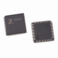
Z85C3008VSG Zilog, Z85C3008VSG Datasheet - Page 21

Z85C3008VSG
Manufacturer Part Number
Z85C3008VSG
Description
IC 8MHZ Z8500 CMOS SCC 44-PLCC
Manufacturer
Zilog
Series
SCCr
Specifications of Z85C3008VSG
Processor Type
Z80
Features
Error Detection and Multiprotocol Support
Speed
8MHz
Voltage
5V
Mounting Type
Surface Mount
Package / Case
44-LCC (J-Lead)
Maximum Operating Temperature
+ 70 C
Minimum Operating Temperature
0 C
Mounting Style
SMD/SMT
Cpu Speed
8MHz
Digital Ic Case Style
LCC
No. Of Pins
44
Supply Voltage Range
5V
Operating Temperature Range
0°C To +70°C
Svhc
No SVHC (18-Jun-2010)
Base Number
85
Rohs Compliant
Yes
Clock Frequency
8MHz
Lead Free Status / RoHS Status
Lead free / RoHS Compliant
Other names
269-3932
Z85C3008VSG
Z85C3008VSG
Available stocks
Company
Part Number
Manufacturer
Quantity
Price
Company:
Part Number:
Z85C3008VSG
Manufacturer:
Zilog
Quantity:
800
Company:
Part Number:
Z85C3008VSG
Manufacturer:
MAX
Quantity:
74
PS011705-0608
INTACK
Interrupt Pending (IP), Interrupt Under Service (IUS), and Interrupt Enable (IE). Opera-
tion of the IE bit is straight forward. If the IE bit is set for a given interrupt source, then
that source can request interrupts. The exception is when the MIE (Master Interrupt
Enable) bit in WR9 is reset and no interrupts can be requested. The IE bits are Write only.
The other two bits are related to the interrupt priority chain (see
cessor peripheral, the SCC can request an interrupt only when no higher priority device is
requesting one, that is, when IEI is High. If the device in question requests an interrupt, it
pulls down INT. The CPU responds with INTACK, and the interrupting device places the
vector on the data bus.
The SCC can also execute an interrupt acknowledge cycle through software. In some CPU
environments, it is difficult to create the INTACK signal with the necessary timing to
acknowledge interrupts and allow the nesting of interrupts. In these cases, the INTACK
signal can be created with a software command to the SCC.
In the SCC, the Interrupt Pending (IP) bit signals a need for interrupt servicing. When an
IP bit is 1 and the IEI input is High, the INT output is pulled Low, requesting an interrupt.
In the SCC, if the IE bit is not set by enabling interrupts, then the IP for that source is
never set. The IP bits are readable in RR3A.
The IUS bits signal that an interrupt request is being serviced. If an IUS is set, all interrupt
sources of lower priority in the SCC and external to the SCC are prevented from request-
ing interrupts.
The internal interrupt sources are inhibited by the state of the internal daisy chain, while
lower priority devices are inhibited by the IEO output of the SCC being pulled Low and
propagated to subsequent peripherals. An IUS bit is set during an Interrupt Acknowl-
edge cycle, if there are no higher priority devices requesting interrupts.
There are three types of interrupts:
D7–D0
•
•
INT
+5 V
Transmit
Receive
IEI D7–D0 INT INTACK IEO
Figure 8. SCC Interrupt Priority Schedule
Peripheral
IEI D7–D0 INT INTACK IEO
CMOS SCC Serial Communications Controller
Peripheral
IEI D7–D0 INT INTACK
Peripheral
Figure
Product Specification
Functional Description
+5 V
8). As a micropro-
17


