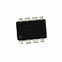
604-00030 Parallax Inc, 604-00030 Datasheet - Page 4

604-00030
Manufacturer Part Number
604-00030
Description
IC FLOATING-POINT COPROC V2 8DIP
Manufacturer
Parallax Inc
Datasheet
1.604-00030.pdf
(17 pages)
Specifications of 604-00030
Processor Type
Floating-Point Co-Processor
Voltage
4.75 V ~ 5.25 V
Mounting Type
Through Hole
Package / Case
*
Product
Microcontroller Accessories
Lead Free Status / RoHS Status
Lead free / RoHS Compliant
Features
-
Speed
-
Lead Free Status / RoHS Status
Lead free / RoHS Compliant, Lead free / RoHS Compliant
I
The Busy/Ready status must always be checked to confirm that the uM-FPU is Ready prior to any read operation.
The Busy status is asserted as soon as a valid opcode is received. The Ready status is asserted when both the
instruction buffer and trace buffer are empty. If the uM-FPU is Ready, a zero byte is returned. If the uM-FPU is
Busy, either executing instructions, or because the debug monitor is active, a 0x80 byte is returned. If more than 32
bytes of data are sent between read operations, the Ready status must also be checked at least once every 32 bytes to
ensure that the instruction buffer does not overflow.
I
Reading I
more advanced interface routines to ensure that the instruction buffer remains fully utilized. It is only used to
determine if there is space to write data to the uM-FPU. The Busy/Ready status must still be used to confirm the
Ready status prior to any read operation.
Read Delay
There is a minimum delay required from the end of a read instruction opcode until the first data byte is ready to be
read. If debug tracing is active, this delay is longer (see table). With many microcontrollers the call overhead for the
interface routines is long enough that no additional delay is required. On faster microcontrollers a suitable delay
must be inserted after a read instruction to ensure that data is valid before the first byte is read. A 180 microsecond
read delay will handle all circumstances (including the debug mode).
Connecting the uM-FPU using the SPI compatible interface
If the CS pin is a logic low at reset (e.g. tied to GND), the uM-FPU will be configured as a SPI slave device. The
uM-FPU can be connected using either a 2-wire or 3-wire SPI interface depending on the capabilities of the
microcontroller. The 3-wire SPI connection uses separate data input and data output pins on the microcontroller.
The 2-wire SPI connection uses a single bidirectional pin for both data input and data output. If a 2-wire SPI
interface is used, the SOUT and SIN pins should not be connected directly together, they must be connected
through a 1K resistor. The microcontroller data pin is connected to the SIN pin. The connection diagrams are
shown below.
Micromega Corporation
2
2
C Busy/Ready Status
C Buffer Space
2
C register 1 will return the number of bytes of free space in the instruction buffer. This can be used by
Microcontroller Pins
DATA
CLK
2-wire SPI Connection
1K
4
1
2
3
4
CS
SOUT
SCLK
VSS
uM-FPU
TS TOUT
TS TIN
VDD
SIN
8
7
6
5
+5V
Resetting and Executing Instructions
uM-FPU V2 Datasheet


