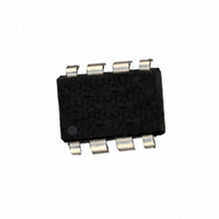
604-00030 Parallax Inc, 604-00030 Datasheet - Page 5

604-00030
Manufacturer Part Number
604-00030
Description
IC FLOATING-POINT COPROC V2 8DIP
Manufacturer
Parallax Inc
Datasheet
1.604-00030.pdf
(17 pages)
Specifications of 604-00030
Processor Type
Floating-Point Co-Processor
Voltage
4.75 V ~ 5.25 V
Mounting Type
Through Hole
Package / Case
*
Product
Microcontroller Accessories
Lead Free Status / RoHS Status
Lead free / RoHS Compliant
Features
-
Speed
-
Lead Free Status / RoHS Status
Lead free / RoHS Compliant, Lead free / RoHS Compliant
SPI Reset Operation
The uM-FPU should be reset at the beginning of every program to ensure that the microcontroller and the uM-FPU
are synchronized. To cause a Reset, the SIN line must be Low while the SCLK line is held High for a minimum of
500 microseconds. The reset operation will not occur until the SCLK line returns Low. A delay of 8 milliseconds is
recommended after the Reset to ensure that the Reset is complete and the uM-FPU is ready to receive commands.
All uM-FPU registers are reset to the special value NaN (Not a Number), which is equal to hexadecimal value
7FC00000.
SPI Reading and Writing Data
The uM-FPU is configured as a Serial Peripheral Interconnect (SPI) slave device. Data is transmitted and received
with the most significant bit (MSB) first using SPI mode 0, summarized as follows:
The maximum SCLK frequency is 4 MHz, but there must be minimum data period between bytes. The minimum
data period is measured from the rising edge of the first bit of one date byte to the rising edge of the first bit of the
next data byte. The minimum data period must elapse before the Busy/Ready status is checked.
Read Delay
There is a minimum delay required from the end of a read instruction opcode until the first data byte is ready to be
read. If debug tracing is active, this delay is longer (see table). With many microcontrollers the call overhead for the
interface routines is long enough that no additional delay is required. On faster microcontrollers a suitable delay
must be inserted after a read instruction to ensure that data is valid before the first byte is read. A 180 microsecond
Micromega Corporation
SCLK is active High (idle state is Low)
Data latched on leading edge of SCLK
Data changes on trailing edge of SCLK
Data is transmitted most significant bit first
SCLK
SIN
Item
Reset - SCLK Output High
Reset - SIN Output Low
Reset Delay
Reset
Microcontroller Pins
DATA OUT
DATA IN
CLK
3-wire SPI Connection
Reset Timing Diagram
Reset Delay
5
Min
500
100
3
1
2
3
4
CS
SOUT
SCLK
VSS
uM-FPU
Typical
TS TOUT
8
TS TIN
VDD
SIN
8
7
6
5
+5V
Max
Resetting and Executing Instructions
msec
Unit
usec
usec
uM-FPU V2 Datasheet


