604-00050 Parallax Inc, 604-00050 Datasheet - Page 16
604-00050
Manufacturer Part Number
604-00050
Description
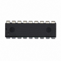
IC FLOATING-PT COPROC V3 18-DIP
Manufacturer
Parallax Inc
Datasheet
1.604-00050.pdf
(36 pages)
Specifications of 604-00050
Processor Type
Floating-Point Co-Processor
Voltage
2.7V ~ 5.5V
Mounting Type
Through Hole
Package / Case
*
Lead Free Status / RoHS Status
Lead free / RoHS Compliant
Features
-
Speed
-
Lead Free Status / RoHS Status
Lead free / RoHS Compliant, Lead free / RoHS Compliant


Mode – set mode parameters
The Mode command is used to set the four interface mode parameter bytes that are stored in Flash memory. The
factory setting of the parameter bytes is all zeros. The parameter bytes are read at reset to determine the mode of
operation. The mode command displays the current parameter values and the user is prompted to enter new values.
(The values are entered as hexadecimal values.) The new values are programmed into Flash memory and the uM-
FPU is Reset.
Two hexadecimal digits represent each parameter byte. The mode parameter bytes are interpreted as follows:
Micromega Corporation
>$M
:00CA0000
Byte 0:
Byte 1: I
Byte 2: Auto-Start Function
Byte 3: reserved
00000000
Bit 7
Bit 6
Bit 5
Bit 4
Bit 3
Bit 2
Bits 1:0 Mode
The 7-bit address is entered as a left justified 8-bit value. The last bit is ignored.
Mode parameter byte 2 now specifies a user-defined function that can optionally be called when
the chip is Reset. Mode parameter byte 2 is only checked at Reset if the CS pin is Low. If both the
CS pin and SERIN pin are High at Reset, Debug Mode will always be entered. To use auto-start
with the I
mode 01 in mode parameter byte 0.
Bit 7
Bit 6
Bit 5:0 Function number
2
Bit
Bit
C Address (if zero, the default address (0xC8) is used.
D F
B R T I
7 6 5 4 3 2 1 0
7 6 5 4 3 2 1 0
Break on Reset (if debug mode is enabled)
use OUT1 pin for Ready/Busy status
Trace on Reset (if debug mode is enabled)
Idle Mode power saving enabled
Sleep Mode power saving enabled
PIC mode enabled (see PICMODE instruction)
00 – CS pin determines interface mode (default)
01 – I
1x – SPI mode selected (CS pin used as chip select)
Debug mode
0 - use SERIN to select debug mode
1 - Disable debug mode
Auto-start function call
0 - No function called
1 - Call the function specified by bits 5:0
2
C interface, the CS pin must be Low at Reset, and the I
2
C mode selected
Function
if CS pin = Low, SPI mode selected
if CS pin = High, I
SERIN = Low, Disable debug mode
SERIN = High, Enable debug mode
S
P Mode
2
C mode selected
16
2
C mode must be selected using
uM-FPU V3.1 Datasheet
Debug Monitor
Related parts for 604-00050
Image
Part Number
Description
Manufacturer
Datasheet
Request
R

Part Number:
Description:
IC ADC 12BIT 8CH MAX1270 24-DIP
Manufacturer:
Parallax Inc
Datasheet:

Part Number:
Description:
IC EMBEDDED USB HOST 48-LQFP
Manufacturer:
Parallax Inc
Datasheet:

Part Number:
Description:
IC SENSOR TOUCH/PROXMTY 1CH 8DIP
Manufacturer:
Parallax Inc
Datasheet:

Part Number:
Description:
IC FLOATING-POINT COPROC V2 8DIP
Manufacturer:
Parallax Inc
Datasheet:


Part Number:
Description:
Microcontroller Modules & Accessories DISCONTINUED BY PARALLAX
Manufacturer:
Parallax Inc

Part Number:
Description:
BOOK UNDERSTANDING SIGNALS
Manufacturer:
Parallax Inc
Datasheet:


Part Number:
Description:
COMPETITION RING FOR SUMOBOT
Manufacturer:
Parallax Inc
Datasheet:


Part Number:
Description:
TEXT INFRARED REMOTE FOR BOE-BOT
Manufacturer:
Parallax Inc
Datasheet:
Part Number:
Description:
BOARD EXPERIMENT+LCD NX-1000
Manufacturer:
Parallax Inc
Datasheet:

Part Number:
Description:
CONTROLLER 16SERVO MOTOR CONTROL
Manufacturer:
Parallax Inc
Datasheet: