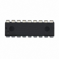
604-00050 Parallax Inc, 604-00050 Datasheet - Page 9

604-00050
Manufacturer Part Number
604-00050
Description
IC FLOATING-PT COPROC V3 18-DIP
Manufacturer
Parallax Inc
Datasheet
1.604-00050.pdf
(36 pages)
Specifications of 604-00050
Processor Type
Floating-Point Co-Processor
Voltage
2.7V ~ 5.5V
Mounting Type
Through Hole
Package / Case
*
Lead Free Status / RoHS Status
Lead free / RoHS Compliant
Features
-
Speed
-
Lead Free Status / RoHS Status
Lead free / RoHS Compliant, Lead free / RoHS Compliant
I
The uM-FPU should be reset at the beginning of every program to ensure that the microcontroller and the uM-FPU
are synchronized. The uM-FPU is reset by writing a zero byte to I
recommended after the reset operation to ensure that the Reset is complete and the uM-FPU is ready to receive
commands. All uM-FPU registers are reset to the special value NaN (Not a Number), which is equal to hexadecimal
value 0x7FC00000.
I
uM-FPU instructions and data are written to I
data is waiting to be transferred. If no data is waiting to be transferred the Busy/Ready status is returned. A read
operation is normally preceded by a write operation to select the I
I
The Busy/Ready status must always be checked to confirm that the uM-FPU is Ready prior to any read operation.
The Busy status is asserted as soon as an instruction byte is received. The Ready status is asserted when both the
instruction buffer and trace buffer are empty. If the uM-FPU is Ready, a zero byte is returned. If the uM-FPU is
Busy, either executing instructions, or because the debug monitor is active, a 0x80 byte is returned. If more than 256
bytes of data are sent between read operations, the Ready status must also be checked at least once every 256 bytes
to ensure that the instruction buffer does not overflow.
I
Reading I
more advanced interface routines to ensure that the instruction buffer remains fully utilized. It is only used to
determine if there is space to write data to the uM-FPU. The Busy/Ready status must still be used to confirm the
Ready status prior to any read operation.
Read Delay
There is a minimum delay (Read Setup Delay) required from the end of a read instruction opcode until the first data
byte is ready to be read. With many microcontrollers the call overhead for the interface routines is long enough that
Micromega Corporation
2
2
2
2
C Reset Operation
C Reading and Writing Data
C Busy/Ready Status
C Buffer Space
2
C register 1 will return the number of bytes of free space in the instruction buffer. This can be used by
Item
I
Read Delay – normal operation
Read Delay – debug enabled
2
C transfer speed
I
2
C Register Address
S 1100100
S - Start Condition
A - ACK
N - NAK
P - Stop Condition
Address
Slave
0
1
1 A
I
2
2
C register 0. Reading I
C Read Data Transfer
I
2
dddddddd
C Registers
Data
9
Write
1 to n data bytes
Reset
Data
A
2
2
C register address 1. A delay of 8 milliseconds is
C register to read from.
2
dddddddd
C register 0 will return the next data byte, if
TBD
TBD
Min
Data
Buffer Space
Data / Status
Connecting to the uM-FPU V3.1
Read
TBD
TBD
Max
400
N
P
uM-FPU V3.1 Datasheet
Unit
usec
usec
kHz


