AHKA21 Panasonic, AHKA21 Datasheet - Page 3
AHKA21
Manufacturer Part Number
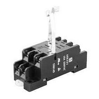
AHKA21
Description
Relay Sockets & Hardware AHK Socket for AHK1 & AHK2
Manufacturer
Panasonic
Datasheet
1.AHK22124.pdf
(8 pages)
Specifications of AHKA21
Accessory Type
Socket
Associated Relay Series
AKH
Number Of Poles
1, 2
Termination Style
Screw
Lead Free Status / Rohs Status
Lead free / RoHS Compliant
Available stocks
Company
Part Number
Manufacturer
Quantity
Price
Company:

Part Number:
AHKA21
Manufacturer:
Panasonic Electric Works
Quantity:
135


RATING
1. Coil data
1) AC coils
Notes: 1. The relay operates in a range of 80% to 110 % V of the voltage rating, but ideally, in consideration of temporary voltage fluctuations, it should be operated at the
2) DC coils (at 20°C 68°F)
Notes) 1. The rated excitation current is ±10% (20°C 68°F).
2. Specifications
Notes: If integrating into electrical appliances that will be subject to compliance to the Electrical Appliance and Material Safety Law, please use in an ambient temperature
Contact
Rating
Electrical
characteristics
Mechanical
characteristics
Expected life
Conditions
Unit weight
Characteristics
100/110V DC
100/110V AC
110/120V AC
200/220V AC
Coil voltage
Coil voltage
12V DC
24V DC
48V DC
12V AC
24V AC
48V AC
2. The maximum allowable voltage is the maximum voltage fluctuation value for the coil power supply. This value is not a permissible value for continuous operation.
2. The coil resistance for DC operation is the value measured when the coil temperature is 20°C 68°F. Compensate ±0.4% for every ±1°C change in temperature.
3. The relay operates in a range of 80% to 110 % V of the voltage rating, but ideally, in consideration of temporary voltage fluctuations, it should be operated at the
4. For use with 200 V DC, connect a 10 KΩ (5W) resistor, in series, to the 100 V DC relay.
5. The maximum allowable voltage is the maximum voltage fluctuation value for the coil power supply. This value is not a permissible value for continuous operation.
between –50°C to +40°C
*1 This value can change due to the switching frequency, environmental conditions and desired reliability level, therefore it is recommended to check this with the
*2 For the AC coil types, the operate/release time will differ depending on the phase.
*3 The upper operation ambient temperature limit is the maximum temperature that can satisfy the coil temperature rise value.Refer to 4. Conditions for operation,
6V DC
rated voltage. In particular, for AC operation, if the impressed voltage drops to 80% V or more below the rated voltage, humming will occur and a large current will
flow leading possibly to coil burnout.
(This value differs depending on the ambient temperature. Please contact us for details.)
rated voltage.
(This value differs depending on the ambient temperature. Please contact us for details.)
actual load.
transport and storage mentioned in AMBIENT ENVIRONMENT.
Initial contact resistance, max
Contact material
Nominal switching capacity
Max. switching voltage
Max. switching current
Min. switching capacity (Reference value)*
Insulation resistance (Initial)
Breakdown voltage
(Initial)
Temperature rise
Operate time (at 20°C 68°F)*
Release time (at 20°C 68°F)*
Shock resistance
Vibration resistance
Mechanical
Electrical
Conditions for operation, transport and storage*
Max. Operating speed
Nominal coil current,
13.4/14.7
12.2/13.5
Nominal coil current,
6.7/7.4
50Hz
111
56
28
18.5
150
mA
–58°F to +104°F
75
37
10
mA
10.9/11.9
12/13.2
60Hz
6/6.6
100
50
25
All Rights Reserved © COPYRIGHT Matsushita Electric Works, Ltd.
Between open contacts
Between contact sets
Between contact and coil
Functional
Destructive
Functional
Destructive
AC load
Item
Nominal operating
(AC type).
Nominal operating power,
2
2
50Hz
power, W
1.3
1.3
1.3
1.3
1.3
1.3
0.9
0.9
0.9
0.9
1.0
V A
1
60Hz
1.2
1.2
1.2
1.2
1.2
1.2
3
Coil resistance,
Max. 50 mΩ (By voltage drop 6 V DC 1A)
AgSnO
1 Form C: 15A 125V AC 2 Form C: 10A 125V AC
250V AC, 125V DC
15A (1 Form C), 10A (2 Form C)
100mA 5V DC
Min. 100MΩ (at 500V DC)
Measurement at same location as “Initial breakdown voltage” section.
1,000 Vrms for 1min. (Detection current: 10mA.)
2,000 Vrms for 1min. (Detection current: 10mA.)
2,000 Vrms for 1min. (Detection current: 10mA.)
Max. 80°C (By resistive method, nominal voltage)
Max. 25ms (Nominal voltage applied to the coil, excluding contact bounce time.)
Max. 25ms (Nominal voltage applied to the coil, excluding contact bounce time.)
(without diode)
Min. 196 m/s
Min. 980 m/s
10 to 55 Hz at double amplitude of 1 mm (Detection time: 10µs.)
10 to 55 Hz at double amplitude of 2 mm
AC type: 5×10
1 Form C: 15A 125V AC (cosϕ=1), Min. 2×10
2 Form C: 10A 125V AC (cosϕ=1), Min. 5×10
Ambient temperature:
–50°C to +70°C
–50°C to +60°C
Humidity: 5 to 85% R.H. (Not freezing and condensing at low temperature)
20 cpm (at max. rating)
Approx. 35g
80%V or less of
nominal voltage
Pick-up voltage
10,000
(at 20°C 68°F)
2,600
160
650
40
Ω
(Initial)
2
type
1.23 oz
2
2
(Half-wave pulse of sine wave: 11 ms; detection time: 10µs.)
(Half-wave pulse of sine wave: 6 ms.)
7
(at 180 cpm), DC type: 10
–58°F to +140°F
–58°F to +158°F
80%V or less of
nominal voltage
Pick-up voltage
30%V or more of
(at 20°C 68°F)
Drop-out voltage
nominal voltage
(at 20°C 68°F)
(Initial)
(Initial)
(With LED indication)
(Without LED indication);
Specifications
8
(at 180 cpm)
5
5
drop-out
When
10%V or more of
0.312
1.243
4.974
23.75
27.19
85.98
Drop-out voltage
nominal voltage
(at 20°C 68°F)
Inductance, H
(Initial)
operating
When
0.295
1.181
4.145
20.63
25.57
81.76
Max. allowable voltage
HK (AHK)
(at 70°C 158°F)
nominal voltage
nominal voltage
Max. allowable
110%V of
110%V of
voltage
Related parts for AHKA21
Image
Part Number
Description
Manufacturer
Datasheet
Request
R

Part Number:
Description:
Coin Cell Battery with Leads 3V 20mAH 2 PIN HORZ
Manufacturer:
Panasonic
Datasheet:
Part Number:
Description:
Coin Cell Battery with Leads 3V 48mAh 2 pin Vert
Manufacturer:
Panasonic
Part Number:
Description:
Coin Cell Battery 3V 12 X 2.5 mm 48mA
Manufacturer:
Panasonic
Datasheet:
Part Number:
Description:
Coin Cell Battery 3V 48mAh W/TABS
Manufacturer:
Panasonic
Datasheet:
Part Number:
Description:
Color CCD Linear Image Sensor with 1024 Pixels for R and B Colors/2048 Pixels for G Color
Manufacturer:
Panasonic
Datasheet:
Part Number:
Description:
2048-Bit CCD Linear Image Sensor
Manufacturer:
Panasonic
Datasheet:
Part Number:
Description:
2592-Bit CCD Linear Image Sensor
Manufacturer:
Panasonic
Datasheet:
Part Number:
Description:
2048-Bit High-Responsivity CCD Linear Image Sensor with Internal Clock Driver
Manufacturer:
Panasonic
Datasheet:
Part Number:
Description:
2880-Bit High-Responsivity CCD Linear Image Sensor
Manufacturer:
Panasonic
Datasheet:
Part Number:
Description:
Color CCD Linear Image Sensor with 512 Pixels for R and B Colors/1024 Pixels for G Color
Manufacturer:
Panasonic
Datasheet:
Part Number:
Description:
Quad analog switches
Manufacturer:
Panasonic
Datasheet:
Part Number:
Description:
ICs for TV
Manufacturer:
Panasonic
Datasheet:
Part Number:
Description:
IC for Liquid Crystal Color TV
Manufacturer:
Panasonic
Datasheet:
Part Number:
Description:
VCR cylinder direct motor drive circuit
Manufacturer:
Panasonic
Datasheet: