AHKA21 Panasonic, AHKA21 Datasheet - Page 8
AHKA21
Manufacturer Part Number
AHKA21
Description
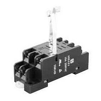
Relay Sockets & Hardware AHK Socket for AHK1 & AHK2
Manufacturer
Panasonic
Datasheet
1.AHK22124.pdf
(8 pages)
Specifications of AHKA21
Accessory Type
Socket
Associated Relay Series
AKH
Number Of Poles
1, 2
Termination Style
Screw
Lead Free Status / Rohs Status
Lead free / RoHS Compliant
Available stocks
Company
Part Number
Manufacturer
Quantity
Price
Company:

Part Number:
AHKA21
Manufacturer:
Panasonic Electric Works
Quantity:
135


HK (AHK)
NOTES
1. Coil operating power
1) DC coil
To ensure proper operation, the voltage
applied to both terminals of the coil
should be ±5% (at 20°C 68°F) the rated
operating voltage of the coil. Also, be
aware that the pick-up and dropout
voltages will fluctuate depending on the
ambient temperature and operating
conditions.
2) AC Coil
To enable stable operation of the relay,
apply the nominal voltage. Ensure that
the fluctuation range of the power source
voltage remains, in principle, within +10%
to –15% of the value of the nominal
current. Moreover, the ideal waveform for
the voltage applied to the coil is a sine
curve. If commercially provided power
surce is used, the waveform should be
checked. If a stabilized AC power source
is used, the conditioning equipment may
distort the waveform, and abnormal
heating may result. With AC coils, hum
can be normally stopped by the use of a
shading coil. If the waveform is distorted,
however, the shading coil may be
ineffective.
2. LED indications
The light of the light emitting diode is
what displays operation. If voltage
remains after relay might illuminate
briefly.
3. Switching lifetime
The switching lifetime is defined under
the standard test condition specified in
the JIS C 5442(*2) standard (temperature
15 to 35°C
75% R.H.). Check this with the real
device as it is affected by coil driving
circuit, load type, activation frequency,
activation phase, ambient conditions and
other factors. Also, be especially careful
of loads such as those listed below.
For Cautions for Use, see Relay Technical Information.
130
59 to
95°F, humidity 25 to
All Rights Reserved © COPYRIGHT Matsushita Electric Works, Ltd.
1) When used for AC load-operating and
the operating phase is synchronous.
Rocking and fusing can easily occur due
to contact shifting.
2) High-frequency load operating
When high-frequency opening and
closing of the relay is performed with a
load that causes arcs at the contacts,
nitrogen and oxygen in the air is fused by
the arc energy and HNO
can corrode metal materials.
Three countermeasures for these are
listed here.
(1) Incorporate an arc-extinguishing
circuit.
(2) Lower the operating frequency
(3) Lower the ambient humidity
4. Conditions for operation, transport and
storage
1) Ambient temperature, humidity, and
atmospheric pressure during usage,
transport, and storage of the relay:
(1) Temperature:
–50 to +70°C (without LED)
–50 to +60°C (with LED)
(2) Humidity: 5 to 85% RH (Avoid
freezing and condensation.)
The humidity range varies with the
temperature. Use within the range
indicated in the graph below.
Temperature and humidity range for
usage, transport, and storage
(3) Atmospheric pressure: 86 to 106kPa
(Avoid freezing when
used at temperatures
lower than 0°C 32°F)
–50
–58
Tolerance range
85
5
+32
0
(Avoid
condensation when
used at temperatures
higher than 0°C 32°F)
Humidity, %R.H.
Temperature, °C
3
is formed. This
°F
+70
+158
2) Condensation
Condensation forms when there is a
sudden change in temperature under
high temperature and high humidity
conditions. Condensation will cause
deterioration of the relay insulation.
3) Freezing
Condensation or other moisture may
freeze on the relay when the
temperatures is lower than 0°C 32°F. This
causes problems such as sticking of
movable parts or operational time lags.
4) Low temperature, low humidity
environments
The plastic becomes brittle if the relay is
exposed to a low temperature, low
humidity environment for long periods of
time.
5. Diode characteristics
1) Reverse breakdown voltage: 1,000 V
2) Forward current: 1 A
6. Diode and CR built-in type
Since the diode and CR inside the relay
coil are designed to absorb the counter
emf, the element may be damaged if a
large surge, etc., is applied to the diode
and CR.
If there is the possibility of a large surge
voltage from the outside, please
implement measures to absorb it
Related parts for AHKA21
Image
Part Number
Description
Manufacturer
Datasheet
Request
R

Part Number:
Description:
Coin Cell Battery with Leads 3V 20mAH 2 PIN HORZ
Manufacturer:
Panasonic
Datasheet:
Part Number:
Description:
Coin Cell Battery with Leads 3V 48mAh 2 pin Vert
Manufacturer:
Panasonic
Part Number:
Description:
Coin Cell Battery 3V 12 X 2.5 mm 48mA
Manufacturer:
Panasonic
Datasheet:
Part Number:
Description:
Coin Cell Battery 3V 48mAh W/TABS
Manufacturer:
Panasonic
Datasheet:
Part Number:
Description:
Color CCD Linear Image Sensor with 1024 Pixels for R and B Colors/2048 Pixels for G Color
Manufacturer:
Panasonic
Datasheet:
Part Number:
Description:
2048-Bit CCD Linear Image Sensor
Manufacturer:
Panasonic
Datasheet:
Part Number:
Description:
2592-Bit CCD Linear Image Sensor
Manufacturer:
Panasonic
Datasheet:
Part Number:
Description:
2048-Bit High-Responsivity CCD Linear Image Sensor with Internal Clock Driver
Manufacturer:
Panasonic
Datasheet:
Part Number:
Description:
2880-Bit High-Responsivity CCD Linear Image Sensor
Manufacturer:
Panasonic
Datasheet:
Part Number:
Description:
Color CCD Linear Image Sensor with 512 Pixels for R and B Colors/1024 Pixels for G Color
Manufacturer:
Panasonic
Datasheet:
Part Number:
Description:
Quad analog switches
Manufacturer:
Panasonic
Datasheet:
Part Number:
Description:
ICs for TV
Manufacturer:
Panasonic
Datasheet:
Part Number:
Description:
IC for Liquid Crystal Color TV
Manufacturer:
Panasonic
Datasheet:
Part Number:
Description:
VCR cylinder direct motor drive circuit
Manufacturer:
Panasonic
Datasheet: