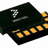
MMA7456LT Freescale Semiconductor, MMA7456LT Datasheet - Page 2

MMA7456LT
Manufacturer Part Number
MMA7456LT
Description
Board Mount Accelerometers 3-AXIS DIGTL 12C&SP1
Manufacturer
Freescale Semiconductor
Series
-r
Datasheet
1.MMA7456LR1.pdf
(35 pages)
Specifications of MMA7456LT
Sensing Axis
X, Y, Z
Acceleration
2 g, 4 g, 8 g
Sensitivity
64 count/g, 32 count/g, 16 count/g
Package / Case
LGA-14
Output Type
Digital
Supply Voltage (max)
3.6 V
Supply Voltage (min)
2.4 V
Supply Current
400 uA
Maximum Operating Temperature
+ 85 C
Minimum Operating Temperature
- 40 C
Axis
X, Y, Z
Acceleration Range
± 2g, 4g, 8g
Voltage - Supply
2.4 V ~ 3.6 V
Bandwidth
6kHz - XY, 3.4kHz - Z
Interface
I²C, SPI
Mounting Type
Surface Mount
Lead Free Status / Rohs Status
Lead free / RoHS Compliant
Available stocks
Company
Part Number
Manufacturer
Quantity
Price
Part Number:
MMA7456LT
Manufacturer:
FREESCALE
Quantity:
20 000
Contents
ELECTRO STATIC DISCHARGE (ESD) ......................................................................................................................................6
PRINCIPLE OF OPERATION ......................................................................................................................................................8
FEATURES ..................................................................................................................................................................................9
Level Detection ...........................................................................................................................................................................10
Threshold Detection for Motion and Freefall Conditions ............................................................................................................11
Pulse Detection ..........................................................................................................................................................................12
Assigning, Clearing & Detecting Interrupts .................................................................................................................................15
Digital Interface ...........................................................................................................................................................................16
BASIC CONNECTIONS .............................................................................................................................................................19
Register Definitions ....................................................................................................................................................................21
Soldering and Mounting Guidelines for the LGA Accelerometer Sensor to a PC Board ............................................................29
Sensors
Freescale Semiconductor
Self-Test .........................................................................................................................................................................9
g-Select ..........................................................................................................................................................................9
Standby Mode ................................................................................................................................................................9
Measurement Mode .......................................................................................................................................................9
$18: Control 1 (Read/Write) Setting the Detection Axes for X, Y and Z .......................................................................10
$19: Control 2 (Read/Write) Motion Detection (OR Condition) or Freefall Detection (AND Condition) ........................10
$18: Control 1 (Read/Write): Setting the threshold to be an integer value or an absolute value .................................10
$1A: Level Detection Threshold Limit Value (Read/Write) ...........................................................................................10
CASE 1: Motion Detection ...........................................................................................................................................11
CASE 2: Motion Detection ...........................................................................................................................................11
CASE 3: Freefall Detection ..........................................................................................................................................11
CASE 4: Freefall Detection ..........................................................................................................................................11
$18: Control 1 (Read/Write): Disable X, Y or Z for Pulse Detection .............................................................................12
$19: Control 2 (Read/Write): Motion Detection (OR condition) or Freefall Detection (AND condition) ........................12
CASE 1: Single Pulse Motion Detection: X or Y or Z > Pulse Threshold for Time < Pulse Duration ..........................12
CASE 2: Freefall Detection: X and Y and Z < Pulse Threshold for Time > Latency Time ...........................................13
CASE 3: Double Pulse Detection: X OR Y OR Z > Threshold for Pulse Duration1 < PDTime1 ...................................14
Clearing the Interrupt Pins: Register $17 .....................................................................................................................15
Detecting Interrupts ......................................................................................................................................................16
I
SPI Slave Interface ......................................................................................................................................................18
Pin Descriptions ...........................................................................................................................................................19
Recommended PCB Layout for Interfacing Accelerometer to Microcontroller .............................................................19
2
C Slave Interface .......................................................................................................................................................16
MMA7456L
2


