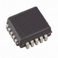
ATF16V8CZ-15JU Atmel, ATF16V8CZ-15JU Datasheet - Page 7

ATF16V8CZ-15JU
Manufacturer Part Number
ATF16V8CZ-15JU
Description
IC PLD 15NS 20PLCC
Manufacturer
Atmel
Datasheet
1.ATF16V8CZ-15PU.pdf
(26 pages)
Specifications of ATF16V8CZ-15JU
Programmable Type
EE PLD
Number Of Macrocells
8
Voltage - Input
5V
Speed
15ns
Mounting Type
Surface Mount
Package / Case
20-PLCC
Logic Family
ATF16V8CZ
Maximum Operating Frequency
62 MHz
Number Of Programmable I/os
8
Delay Time
15 ns
Operating Supply Voltage
5 V
Supply Current
105 mA
Maximum Operating Temperature
+ 85 C
Minimum Operating Temperature
- 40 C
Mounting Style
SMD/SMT
Number Of Product Terms Per Macro
8
Supply Voltage (max)
5.5 V
Supply Voltage (min)
4.5 V
Logic Type
EEPLD
Propagation Delay
15ns
No. Of I/o's
8
Frequency
62MHz
Supply Current Max
105mA
Supply Voltage Range
4.5V To 5.5V
Operating Temperature Range
-40°C To +85°C
Rohs Compliant
Yes
Lead Free Status / RoHS Status
Lead free / RoHS Compliant
Available stocks
Company
Part Number
Manufacturer
Quantity
Price
Part Number:
ATF16V8CZ-15JU
Manufacturer:
MICROCHIP/微芯
Quantity:
20 000
4.5
4.6
5. Security Fuse Usage
0453H–PLD–7/05
Power-up Reset
Preload of Registered Outputs
The ATF16V8CZ’s registers are designed to reset during power-up. At a point delayed slightly
from V
put state will always be high on power-up.
This feature is critical for state machine initialization. However, due to the asynchronous nature
of reset and the uncertainty of how V
required:
The ATF16V8CZ’s registers are provided with circuitry to allow loading of each register with
either a high or a low. This feature will simplify testing since any state can be forced into the reg-
isters to control test sequencing. A JEDEC file with preload is generated when a source file with
vectors is compiled. Once downloaded, the JEDEC file preload sequence will be done automati-
cally by approved programmers.
A single fuse is provided to prevent unauthorized copying of the ATF16V8CZ fuse patterns.
Once programmed, fuse verify and preload are inhibited. However, the 64-bit User Signature
remains accessible.
The security fuse should be programmed last, as its effect is immediate.
Parameter
t
V
1. The V
2. After reset occurs, all input and feedback setup times must be met before driving the
3. The signals from which the clock is derived must remain stable during t
PR
RST
clock term high, and
CC
crossing V
CC
rise must be monotonic, from below 0.7V,
RST
Description
Power-up Reset Time
Power-up Reset Voltage
, all registers will be reset to the low state. As a result, the registered out-
CC
actually rises in the system, the following conditions are
Typ
600
3.8
ATF16V8CZ
1,000
Max
4.5
PR
.
Units
ns
V
7


