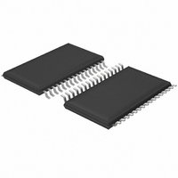
UDA1380TT/N2,518 NXP Semiconductors, UDA1380TT/N2,518 Datasheet - Page 48

UDA1380TT/N2,518
Manufacturer Part Number
UDA1380TT/N2,518
Description
IC AUDIO CODER-DECODER 32-TSSOP
Manufacturer
NXP Semiconductors
Type
Stereo Audior
Datasheet
1.UDA1380HNN2118.pdf
(68 pages)
Specifications of UDA1380TT/N2,518
Data Interface
I²C, Serial
Resolution (bits)
24 b
Number Of Adcs / Dacs
2 / 2
Sigma Delta
No
S/n Ratio, Adcs / Dacs (db) Typ
97 / 100
Voltage - Supply, Analog
2.4 V ~ 3.6 V
Voltage - Supply, Digital
2.4 V ~ 3.6 V
Operating Temperature
-40°C ~ 85°C
Mounting Type
Surface Mount
Package / Case
32-TSSOP
Lead Free Status / RoHS Status
Lead free / RoHS Compliant
Other names
935270659518
UDA1380TT-T
UDA1380TT-T
UDA1380TT-T
UDA1380TT-T
NXP Semiconductors
Table 63 AGC target level setting bits
11.15 Restore L3 default values (software reset)
Table 64 Register address 7FH
11.16 Headphone driver and interpolation filter (read-out)
Table 65 Register address 18H
Table 66 Description of register bits
2004 Apr 22
Default value
Default value
Symbol
Symbol
Stereo audio coder-decoder
for MD, CD and MP3
15 to 11
BIT
BIT
BIT
BIT
BIT
AGC_LEVEL1
10
9
8
7
6
5
0
0
1
1
−
HP_STCTV
HP_STCTL
HP_STCTR
−
SDETR2
SDETL2
15
15
−
7
−
−
7
−
SYMBOL
SDETR2
AGC_LEVEL0
14
14
6
6
−
−
−
0
1
0
1
not used
Headphone driver short-circuit detection. When this bit is logic 0:
headphone driver is not short-circuit protected. When this bit is logic 1:
headphone driver short-circuit protection is activated.
Left headphone driver short-circuit detection. When this bit is logic 0: left
channel headphone driver is not short-circuit protected. When this bit is
logic 1: left channel headphone driver short-circuit protection is activated.
Right headphone driver short-circuit detection. When this bit is logic 0:
right channel headphone driver not short-circuit protected. When this bit is
logic 1: right channel headphone driver short-circuit protection activated.
not used
Interpolator silence detect channel 2 right. When this bit is logic 0:
interpolator on channel 2 right input has detected no silence. When this bit is
logic 1: interpolator on channel 2 right input has detected silence.
Interpolator silence detect channel 2 left. When this bit is logic 0:
interpolator on channel 2 left input has detected no silence. When this bit is
logic 1: interpolator on channel 2 left input has detected silence.
SDETL2
13
13
−
5
−
−
5
SDETR1
12
12
−
4
−
−
4
48
SDETL1
AGC TARGET LEVEL VALUE (dBFS)
11
11
−
3
−
−
3
DESCRIPTION
HP_STCTV
STATE_M
MUTE_
−5.5 (default)
10
10
−
2
−
2
−11.5
−14
−8
STATE_CH2
HP_STCTL
MUTE_
9
−
1
−
9
1
Product specification
UDA1380
STATE_CH1
HP_STCTR
MUTE_
8
−
0
−
8
0


