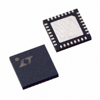
LTC1955EUH Linear Technology, LTC1955EUH Datasheet - Page 16

LTC1955EUH
Manufacturer Part Number
LTC1955EUH
Description
IC INTERFACE DL SMART CARD 32QFN
Manufacturer
Linear Technology
Datasheet
1.LTC1955EUHPBF.pdf
(20 pages)
Specifications of LTC1955EUH
Controller Type
Smart Card Interface
Interface
4-Wire Serial
Voltage - Supply
1.7 V ~ 5.5 V
Current - Supply
10µA
Operating Temperature
-40°C ~ 85°C
Mounting Type
Surface Mount
Package / Case
32-QFN
Lead Free Status / RoHS Status
Contains lead / RoHS non-compliant
Available stocks
Company
Part Number
Manufacturer
Quantity
Price
Company:
Part Number:
LTC1955EUH
Manufacturer:
LT
Quantity:
10 000
Part Number:
LTC1955EUH
Manufacturer:
LINEAR/凌特
Quantity:
20 000
Company:
Part Number:
LTC1955EUH#PBF
Manufacturer:
ADI
Quantity:
5
Part Number:
LTC1955EUH#PBF
Manufacturer:
LINEAR/凌特
Quantity:
20 000
Part Number:
LTC1955EUH#TRPBF
Manufacturer:
LINEAR/凌特
Quantity:
20 000
APPLICATIONS INFORMATION
LTC1955
Using S.A.M. Cards
For applications using one or more installed S.A.M.
cards, the PRES A/PRES B pins for those sockets must
be grounded before operation of the card can occur
(assuming NC/NO is grounded). The PRES A/PRES B
pull-up current is designed for very low consumption,
but ultralow current can be achieved in shutdown by us-
ing a microcontroller output to pull down on the PRES
A/PRES B pins only when communication is necessary.
The fault detection circuitry will not allow a card socket
to be operated unless a card is detected.
Asynchronous Channel A Card Detection
Since the shift register is transparent when LD is held
low, D
D15 indicates the status of the card detection channel for
channel A. Thus, it is not necessary to perform an entire
read/write operation to determine the card detection
status of channel A. With LD low, D
generate a real time card detection interrupt. This could be
useful for one S.A.M. card, one smart card application.
Inter Card Communication
Communication is possible directly from one card socket
to the other when both cards are selected at the same
time. This can be achieved by the following sequence of
actions.
1. Start with both cards off and deselected
2. Activate the supply of the slave card
3. Select the slave card only
4. Initiate a reset on the slave card
5. Deselect the slave card
6. Activate the supply of the master card
7. Select the master card only
8. Initiate a reset on the master card
9. Select both cards
16
OUT
is the same as D15. Recall from Table 1 that
OUT
can be used to
Using the UNDERV Pin
The UNDERV pin can be used to add protection against a
supply undervoltage fault. By using two external program-
ming resistors, the undervoltage detection can be set to an
arbitrary level (Figure 7). To ensure that the smart cards
are properly shut down, there must be suffi cient energy
available in the input bypass capacitor to run one or both
smart cards until the deactivation cycle begins. It can take
approximately 30μs from the detection of a fault until the
deactivation sequence begins. It is desirable to maintain
the V
Consider the following (worst-case) example:
1. The UNDERV pin is programmed to trip below 3.1V.
2. It is possible to have both cards activated at 5V and
Since the output voltage is programmed to 5V, the charge
pump will be acting as a voltage doubler. With two cards
drawing 60mA each, the input current will be 2 • (60mA
+ 60mA), or about 240mA. Allowing the V
droop from 3.1V to 2.7V during the 30μs timeout period,
the input capacitance would need to be at least:
Thermal Management
To minimize power dissipation, the LTC1955 will actively
decide whether to step up or down depending on the
required output voltages and available input voltage.
However, for optimum effi ciency, the LTC1955 should be
powered from a 3.3V supply.
If the input voltage is above 3.6V, and both cards are
drawing maximum current, there can be substantial power
dissipation in the LTC1955. If the junction temperature in-
creases above approximately 150°C, the thermal shutdown
circuitry will automatically deactivate both channels. To
reduce the maximum junction temperature, a good thermal
connection to the PC board is recommended.
Zero Shutdown Current
Although the LTC1955 is designed to have very low shut-
down current, it can still draw over a microampere on both
drawing 60mA.
240mA / [(3.1V – 2.7V) / 30μs] or 18μF .
BATT
supply at 2.7V or greater during this period.
BATT
supply to
1955fb


