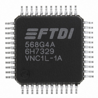
VNC1L-1A-REEL FTDI, Future Technology Devices International Ltd, VNC1L-1A-REEL Datasheet - Page 14

VNC1L-1A-REEL
Manufacturer Part Number
VNC1L-1A-REEL
Description
IC USB HOST CTLR VINCULUM 48LQFP
Manufacturer
FTDI, Future Technology Devices International Ltd
Series
Vinculumr
Datasheet
1.VNC1L-1A-REEL.pdf
(32 pages)
Specifications of VNC1L-1A-REEL
Controller Type
USB 2.0 Controller
Interface
SPI
Voltage - Supply
3 V ~ 3.6 V
Current - Supply
25mA
Operating Temperature
0°C ~ 70°C
Mounting Type
Surface Mount
Package / Case
48-LQFP
For Use With
768-1006 - BOARD DEV FOR VINCULUM VNC1L-1A768-1005 - MOD USB FLASH DISK FILE TRANSFER768-1002 - MOD MCU-USB HOST CTLR 40-DIP768-1001 - MOD MCU-USB HOST CTLR 24-DIP27937 - MEMORY STICK DATALOGGER
Lead Free Status / RoHS Status
Lead free / RoHS Compliant
Other names
768-1000-2
Available stocks
Company
Part Number
Manufacturer
Quantity
Price
Company:
Part Number:
VNC1L-1A-REEL
Manufacturer:
TI
Quantity:
3 485
Part Number:
VNC1L-1A-REEL
Manufacturer:
FTDI
Quantity:
20 000
5
There are three firmware interface options for the command monitor on the combined control and data
interface. The command monitor interface options are UART, FIFO or SPI. The mode of operation is
selected using VNC1L pins 46 and 47.The pin connections used to select the mode of the interface are
shown in Table 5.1:
Table 5.1 Combined Interface Selection
Important : Pins ACBUS5 and ACBUS6 should not be tied directly to GND or VCC.
Pins ACBUS5 and ACBUS6 should be pulled high or low using a resistor of around 47kΩ. These pins are
read only at reset, but may then become outputs after the interface choice has been selected. When FIFO
mode is selected ACBUS5 will be used as an output by VNC1L Firmware.
5.1 UART Interface
When the data and control buses are configured in UART mode, the interface implements a standard
asynchronous serial UART port with flow control. The UART can support baud rates from 300baud to
1Mbaud.
Data transfer uses NRZ (Non-Return to Zero) data format consisting of 1 start bit, 7 or 8 data bits, an
optional parity bit, and one or two stop bits. When transmitting the data bits, the least significant bit is
transmitted first. Transmit and receive waveforms are illustrated in Figure 5.1 and Figure 5.2:
.
Figure 5.1 UART Receive Waveform
Figure 5.2 UART Transmit Waveform
Baud rate (default =9600 baud), flow control settings (default = RTS/CTS), number of data bits
(default=8), parity (default is no parity) and number of stop bits (default=1) are all configurable using
the firmware command interface. Please refer to
Firmware Control Interface
Pull-Down
Pull-Down
(ACBUS6)
Pull-Up
Pull-Up
47
Pin No.
Copyright © 2009 Future Technology Devices International Limited
Pull-Down
Pull-Down
(ACBUS5)
Pull-Up
Pull-Up
46
Vinculum VNC1L Embedded USB Host Controller IC Datasheet Version 2.02
http://www.ftdichip.com
UART
UART
Mode
FIFO
SPI
Document Reference No.: FT_000030
(or latest version).
Clearance No.: FTDI# 50
14


