ULQ-1.5/25-D24PM-C Murata Power Solutions Inc, ULQ-1.5/25-D24PM-C Datasheet - Page 4
ULQ-1.5/25-D24PM-C
Manufacturer Part Number
ULQ-1.5/25-D24PM-C
Description
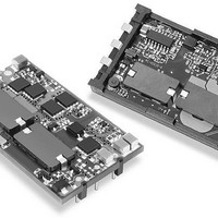
DC/DC Converters & Regulators 37.5W 24Vto1.5V 25A POS SURFACE MOUNT
Manufacturer
Murata Power Solutions Inc
Series
ULQr
Datasheet
1.ULQ-1210-D48PM-C.pdf
(16 pages)
Specifications of ULQ-1.5/25-D24PM-C
Product
Isolated
Output Power
38 W
Input Voltage Range
18 V to 36 V
Input Voltage (nominal)
24 V
Number Of Outputs
1
Output Voltage (channel 1)
1.5 V
Output Current (channel 1)
25 A
Isolation Voltage
2.25 KV
Package / Case Size
Quarter Brick
Lead Free Status / Rohs Status
Lead free / RoHS Compliant
Other names
ULQ-1.5/25-D24PM-C


T E C H N I C A L N O T E S
Input Fusing
Certain applications and/or safety agencies may require the installation of
fuses at the inputs of power conversion components. Fuses should also be
used if the possibility of sustained, non-current-limited, input-voltage polarity
reversals exists. For DATEL ULQ series DC/DC converters, we recommend
the use of a time delay fuse, installed in the ungrounded input supply line,
with a value no greater than 20 Amps.
As a rule of thumb however, we recommend the use of a normal-blow or
slow-blow fuse with a typical value about twice the maximum input current,
calculated at low line with the converter's minimum effi ciency.
All relevant national and international safety standards and regulations must
be observed by the installer. For system safety agency approvals, the
converters must be installed in compliance with the requirements of the end-
use safety standard, i.e. IEC/EN/UL60950.
Input Reverse-Polarity Protection
If the input voltage polarity is accidentally reversed, an internal diode will
become forward biased and likely draw excessive current from the power
source. If this source is not current limited or the circuit appropiately fused, it
could cause permanent damage to the converter.
Input Undervoltage Shutdown and Start-Up Threshold
Under normal start-up conditions, devices will not begin to regulate properly
until the ramping-up input voltage exceeds the Start-Up Threshold Voltage.
Once operating, devices will not turn off until the input voltage drops below
the Undervoltage Shutdown limit. Subsequent re-start will not occur until the
input is brought back up to the Start-Up Threshold. This built in hysteresis
prevents any unstable on/off situations from occurring at a single input
voltage.
Start-Up Time
The V
the ramping input voltage crosses the Start-Up Threshold and the fully loaded
output voltage enters and remains within its specifi ed accuracy band. Actual
measured times will vary with input source impedance, external input capaci-
tance, and the slew rate and fi nal value of the input voltage as it appears at
the converter. The ULQ Series implements a soft start circuit to limit the duty
cycle of its PWM controller at power up, thereby limiting the input inrush current.
The On/Off Control to V
nominal input voltage applied but is turned off via the On/Off Control pin. The
specifi cation defi nes the interval between the point at which the converter is
turned on (released) and the fully loaded output voltage enters and remains
within its specifi ed accuracy band.
Similar to the V
time is also governed by the internal soft start circuitry and external load
capacitance. The difference in start up time from V
Control to V
Input Overvoltage Shutdown
All 24V
voltages exceeding the input overvoltage shutdown specifi cation listed in the
Performance/Functional Specifi cations will cause the device to shutdown.
IN
IN
to V
ULQ DC/DC's are equipped with input overvoltage protection. Input
OUT
OUT
IN
Start-Up Time is the time interval between the point at which
is therefore insignifi cant.
to V
OUT
OUT
start-up, the On/Off Control to V
start-up time assumes the converter has its
IN
to V
OUT
OUT
and from On/Off
start-up
www.murata-ps.com
A built-in hysterisis for all models will not allow the converter to restart until
the input voltage is suffi ciently reduced.
All 48V
on requirements to withstand brief input surges and transients to 100V for
up to 100msec without voltage interruption. Contact DATEL to have input
overvoltage shutdown for 48V
Input Source Impedance
The input of ULQ converters must be driven from a low ac-impedance
source. The DC/DC's performance and stability can be compromised by
the use of highly inductive source impedances. The input circuit shown in
Figure 2 is a practical solution that can be used to minimize the effects of
inductance in the input traces. For optimum performance, components should
be mounted close to the DC/DC converter.
I/O Filtering, Input Ripple Current, and Output Noise
All models in the ULQ Series are tested/specifi ed for input refl ected
ripple current and output noise using the specifi ed external input/output
components/circuits and layout as shown in the following two fi gures. External
input capacitors (C
minimizing line voltage variations caused by transient IR drops in conductors
from backplane to the DC/DC. Input caps should be selected for bulk capaci-
tance (at appropriate frequencies), low ESR, and high rms-ripple-current
ratings. The switching nature of DC/DC converters requires that dc voltage
sources have low ac impedance as highly inductive source impedance can
affect system stability. In Figure 2, C
voltage bus. Your specifi c system confi guration may necessitate additional
considerations.
In critical applications, output ripple/noise (also referred to as periodic and
random deviations or PARD) may be reduced below specifi ed limits using fi l-
tering techniques, the simplest of which is the installation of additional exter-
nal output capacitors. They function as true fi lter elements and should be
selected for bulk capacitance, low ESR and appropriate frequency response.
All external capacitors should have appropriate voltage ratings and be
located as close to the converter as possible. Temperature variations for all
relevant parameters should also be taken carefully into consideration. The
most effective combination of external I/O capacitors will be a function of
line voltage and source impedance, as well as particular load and layout
conditions. Our Applications Engineers can recommend potential solutions
and discuss the possibility of our modifying a given device's internal fi ltering
to meet your specifi c requirements. Contact our Applications Engineering
Group for additional details.
V
OSCILLOSCOPE
IN
–
+
IN
models have the overvoltage shutdown function disabled, based
C
C
L
TO
BUS
IN
BUS
= 33μF, ESR < 700mΩ @ 100kHz
= 12μH
= 220μF, ESR < 100mΩ @ 100kHz
Single Output, Low-Profi le, Quarter-Brick
IN
Figure 2. Measuring Input Ripple Current
C
in Figure 2) serve primarily as energy-storage elements,
BUS
8-25 Amp Isolated DC/DC Converters
L
BUS
IN
models enabled.
21 Feb 2011 MDC_ULQ-15A.B03 Page 4 of 16
BUS
CURRENT
PROBE
and L
C
IN
BUS
ULQ Models
simulate a typical dc
email: sales@murata-ps.com
3
1
+INPUT
–INPUT
Related parts for ULQ-1.5/25-D24PM-C
Image
Part Number
Description
Manufacturer
Datasheet
Request
R

Part Number:
Description:
DC/DC Converters & Regulators 37.5W 48Vto1.5V 25A NEG SURFACE MOUNT
Manufacturer:
Murata Power Solutions Inc
Datasheet:
Part Number:
Description:
DC/DC Converters & Regulators 37.5W 24Vto1.5V 25A NEG SURFACE MOUNT
Manufacturer:
Murata Power Solutions Inc
Part Number:
Description:
DC/DC TH 25A 24-1.5V Q-Brick
Manufacturer:
Murata Power Solutions Inc
Datasheet:
Part Number:
Description:
DC/DC TH 25A 24-1.5V Q-Brick
Manufacturer:
Murata Power Solutions Inc
Datasheet:
Part Number:
Description:
DC/DC TH 25A 48-1.5V Q-Brick
Manufacturer:
Murata Power Solutions Inc
Datasheet:
Part Number:
Description:
DC/DC TH 25A 48-1.5V Q-Brick
Manufacturer:
Murata Power Solutions Inc
Datasheet:
Part Number:
Description:
DC/DC TH 15A 48-1.5V Q-Brick
Manufacturer:
Murata Power Solutions Inc
Datasheet:
Part Number:
Description:
DC/DC TH 15A 48-1.5V Q-Brick
Manufacturer:
Murata Power Solutions Inc
Datasheet:

Part Number:
Description:
POWER OVER ETHERNET MODULE
Manufacturer:
Murata Power Solutions Inc
Datasheet:

Part Number:
Description:
POWER OVER ETHERNET MODULE
Manufacturer:
Murata Power Solutions Inc
Datasheet:
Part Number:
Description:
DC/DC TH 10A 48-12V Q-Brick
Manufacturer:
Murata Power Solutions Inc

Part Number:
Description:
Transformers 5Vin 5Vout 200mA 4000Vdc 1:1.33 turn
Manufacturer:
Murata Power Solutions Inc
Datasheet:

Part Number:
Description:
POWER SUPPLY
Manufacturer:
Murata Power Solutions Inc
Datasheet:

Part Number:
Description:
DPM LED MINI 2VDC 3.5DIG LP RED
Manufacturer:
Murata Power Solutions Inc
Datasheet:

Part Number:
Description:
CONV DC/DC 1W 5VIN 5VOUT SIP SGL
Manufacturer:
Murata Power Solutions Inc
Datasheet: