ULQ-1.5/25-D24PM-C Murata Power Solutions Inc, ULQ-1.5/25-D24PM-C Datasheet - Page 6
ULQ-1.5/25-D24PM-C
Manufacturer Part Number
ULQ-1.5/25-D24PM-C
Description
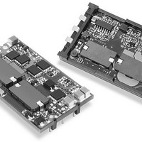
DC/DC Converters & Regulators 37.5W 24Vto1.5V 25A POS SURFACE MOUNT
Manufacturer
Murata Power Solutions Inc
Series
ULQr
Datasheet
1.ULQ-1210-D48PM-C.pdf
(16 pages)
Specifications of ULQ-1.5/25-D24PM-C
Product
Isolated
Output Power
38 W
Input Voltage Range
18 V to 36 V
Input Voltage (nominal)
24 V
Number Of Outputs
1
Output Voltage (channel 1)
1.5 V
Output Current (channel 1)
25 A
Isolation Voltage
2.25 KV
Package / Case Size
Quarter Brick
Lead Free Status / Rohs Status
Lead free / RoHS Compliant
Other names
ULQ-1.5/25-D24PM-C


Output overvoltage protection is monitored at the output voltage pin, not the
Sense pin. Therefore, excessive voltage differences between V
in conjunction with trim adjustment of the output voltage can cause the over-
voltage protection circuitry to activate (see Performance Specifi cations for
overvoltage limits). Power derating is based on maximum output current and
voltage at the converter's output pins. Use of trim and sense functions can
cause output voltages to increase, thereby increasing output power beyond
the conveter's specifi ed rating, or cause output voltages to climb into the
output overvoltage region. Therefore, the designer must ensure:
Trimming Output Voltage
ULQ converters have a trim capability (pin 6) that enables users to adjust
the output voltage from +10% to –20% (refer to the trim equations and trim
graphs that follow). Adjustments to the output voltage can be accomplished
via a trim pot (Figure 5) or a single fi xed resistor as shown in Figures 6 and 7.
A single fi xed resistor can increase or decrease the output voltage depending
on its connection. Resistors should be located close to the converter and
have TCR's less than 100ppm/°C to minimize sensitivity to changes in
temperature. If the trim function is not used, leave the trim pin open.
Figure 7. Trim Connections To Decrease Output Voltages Using Fixed Resistors
Figure 6. Trim Connections To Increase Output Voltages Using Fixed Resistors
(V
1
2
3
1
2
3
1
2
3
OUT
–INPUT
ON/OFF
CONTROL
+INPUT
–INPUT
ON/OFF
CONTROL
+INPUT
–INPUT
ON/OFF
CONTROL
+INPUT
Figure 5. Trim Connections Using A Trimpot
at pins) × (I
OUT
+OUTPUT
–OUTPUT
+OUTPUT
–OUTPUT
+OUTPUT
–OUTPUT
+SENSE
–SENSE
) ≤ rated output power
+SENSE
–SENSE
+SENSE
–SENSE
TRIM
TRIM
TRIM
8
7
5
6
4
8
7
8
7
6
5
4
6
5
4
R
TRIM DOWN
R
TRIM UP
TURNS
5-22
LOAD
LOAD
LOAD
OUT
www.murata-ps.com
and Sense
A single resistor connected from the Trim pin (pin 6) to the +Sense (pin 7) will
increase the output voltage. A resistor connected from the Trim Pin (pin 6) to
the –Sense (pin 5) will decrease the output voltage.
Trim adjustments greater than the specifi ed +10%/–20% can have an
adverse affect on the converter’s performance and are not recommended.
Excessive voltage differences between V
trim adjustment of the output voltage, can cause the overvoltage protection
circuitry to activate (see Performance Specifi cations for overvoltage limits).
Temperature/power derating is based on maximum output current and volt-
age at the converter's output pins. Use of the trim and sense functions can
cause output voltages to increase, thereby increasing output power beyond
the converter's specifi ed rating, or cause output voltages to climb into the
output overvoltage region. Therefore:
The Trim pin (pin 6) is a relatively high impedance node that can be suscep-
tible to noise pickup when connected to long conductors in noisy environ-
ments. In such cases, a 0.22μF capacitor can be added to reduce this long
lead effect.
Note: Resistor values are in kΩ. Adjustment accuracy is subject to resistor
tolerances and factory-adjusted output accuracy. V
R
R
R
R
R
R
R
R
T
T
T
T
T
T
T
T
UP
UP
UP
UP
UP
UP
UP
UP
(kΩ) =
(kΩ) =
(kΩ) =
(kΩ) =
(kΩ) =
(kΩ) =
(kΩ) =
(kΩ) =
(V
OUT
Single Output, Low-Profi le, Quarter-Brick
at pins) x (I
1.308(V
6.23(V
7.44(V
8.28(V
13.3(V
20.4(V
49.6(V
10(V
V
V
V
V
V
V
V
V
O
O
O
O
O
O
O
O
8-25 Amp Isolated DC/DC Converters
O
O
O
O
O
O
O
O
– 1.2
ULQ-1.5/15-D48, ULQ-1.5/25-D24 & D48
ULQ-1.8/15-D48, ULQ-1.8/25-D24 & D48
ULQ-1.2/15-D48 & ULQ-1.2/25-D48
– 1.5
– 1.8
ULQ-2.5/15-D48, ULQ-2.5/20-D24 & D48
– 1.226)
– 2.5
ULQ-3.3/15-D48, ULQ-3.3/20-D24 & D48
– 3.3
– 12
– 2
– 1.226)
– 5
– 1.226)
– 1.226)
– 1.226)
– 1.226)
– 1.226)
– 0.793)
ULQ-2/15-D48, ULQ-2/15-D24 & D48
ULQ-12/8-D24, ULQ-12/10-D48
Trim Equations
OUT
) ≤ rated output power
ULQ-5/15-D24, -D48
–1.413
–10.2
–10.2
–10.2
–10.2
–10.2
–10.2
–10.2
21 Feb 2011 MDC_ULQ-15A.B03 Page 6 of 16
OUT
R
R
R
R
R
R
R
R
T
T
T
T
T
T
T
T
and Sense, in conjunction with
DOWN
DOWN
DOWN
DOWN
DOWN
DOWN
DOWN
DOWN
ULQ Models
email: sales@murata-ps.com
(kΩ) =
(kΩ) =
(kΩ) =
(kΩ) =
(kΩ) =
(kΩ) =
(kΩ) =
(kΩ) =
O
= desired output voltage.
1.2 – V
1.5 – V
1.8 – V
2.5 – V
3.3 – V
12 – V
5 – V
2 – V
1.037
10.15
12.26
16.31
25.01
60.45
7.64
9.12
O
O
O
O
O
O
O
O
–1.413
–10.2
–10.2
–10.2
–10.2
–10.2
–10.2
–10.2
Related parts for ULQ-1.5/25-D24PM-C
Image
Part Number
Description
Manufacturer
Datasheet
Request
R

Part Number:
Description:
DC/DC Converters & Regulators 37.5W 48Vto1.5V 25A NEG SURFACE MOUNT
Manufacturer:
Murata Power Solutions Inc
Datasheet:
Part Number:
Description:
DC/DC Converters & Regulators 37.5W 24Vto1.5V 25A NEG SURFACE MOUNT
Manufacturer:
Murata Power Solutions Inc
Part Number:
Description:
DC/DC TH 25A 24-1.5V Q-Brick
Manufacturer:
Murata Power Solutions Inc
Datasheet:
Part Number:
Description:
DC/DC TH 25A 24-1.5V Q-Brick
Manufacturer:
Murata Power Solutions Inc
Datasheet:
Part Number:
Description:
DC/DC TH 25A 48-1.5V Q-Brick
Manufacturer:
Murata Power Solutions Inc
Datasheet:
Part Number:
Description:
DC/DC TH 25A 48-1.5V Q-Brick
Manufacturer:
Murata Power Solutions Inc
Datasheet:
Part Number:
Description:
DC/DC TH 15A 48-1.5V Q-Brick
Manufacturer:
Murata Power Solutions Inc
Datasheet:
Part Number:
Description:
DC/DC TH 15A 48-1.5V Q-Brick
Manufacturer:
Murata Power Solutions Inc
Datasheet:

Part Number:
Description:
POWER OVER ETHERNET MODULE
Manufacturer:
Murata Power Solutions Inc
Datasheet:

Part Number:
Description:
POWER OVER ETHERNET MODULE
Manufacturer:
Murata Power Solutions Inc
Datasheet:
Part Number:
Description:
DC/DC TH 10A 48-12V Q-Brick
Manufacturer:
Murata Power Solutions Inc

Part Number:
Description:
Transformers 5Vin 5Vout 200mA 4000Vdc 1:1.33 turn
Manufacturer:
Murata Power Solutions Inc
Datasheet:

Part Number:
Description:
POWER SUPPLY
Manufacturer:
Murata Power Solutions Inc
Datasheet:

Part Number:
Description:
DPM LED MINI 2VDC 3.5DIG LP RED
Manufacturer:
Murata Power Solutions Inc
Datasheet:

Part Number:
Description:
CONV DC/DC 1W 5VIN 5VOUT SIP SGL
Manufacturer:
Murata Power Solutions Inc
Datasheet: