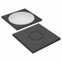
DS31412 Maxim Integrated Products, DS31412 Datasheet - Page 34

DS31412
Manufacturer Part Number
DS31412
Description
IC 12CH DS3/3 FRAMER 349-BGA
Manufacturer
Maxim Integrated Products
Datasheet
1.DS3148.pdf
(89 pages)
Specifications of DS31412
Controller Type
DS3/E3 Framer
Interface
LIU
Voltage - Supply
3.135 V ~ 3.465 V
Current - Supply
960mA
Operating Temperature
-40°C ~ 85°C
Mounting Type
Surface Mount
Package / Case
349-BGA
Lead Free Status / RoHS Status
Lead free / RoHS Compliant
Available stocks
Company
Part Number
Manufacturer
Quantity
Price
Bit 3: DS3/E3 Transmit Alarm Indication Signal (TAIS). When this bit is logic 1 in DS3 mode, the transmitter
generates DS3 AIS, which is a properly F-bit and M-bit framed 1010... data pattern with both X bits set to 1, all C
bits set to 0, and the proper P bits. When this bit is logic 1 in E3 mode, the transmitter generates an unframed all-
ones pattern. When this bit is logic 0, normal data is transmitted.
Bit 4: DS3/E3 Transmit Remote Alarm Indication (TRAI). When this bit is logic 1 in DS3 mode, both X bits of
each DS3 frame are set to logic 0. When this bit is logic 1 in E3 mode, the RAI bit (bit 11 of each E3 frame) is set to
logic 1. When this bit is logic 0 in DS3 mode, both X bits are set to logic 1. When this bit is logic 0 in E3 mode, the
RAI bit is set to logic 0.
Bit 5: Transmit DS3 Idle Signal Enable (T3IDLE). When this bit is logic 1 in DS3 mode, the transmitter generates
the DS3 idle signal instead of the normal transmit data. The DS3 idle signal is defined as a normally DS3 framed
pattern (i.e., with the proper F bits and M bits along with the proper P bits) where the information bit fields are
completely filled with a data pattern of 1100..., the C bits in Subframe 3 are set to logic 0, and both X bits are set to
logic 1. In C-Bit Parity mode, the PMDL and FEAC channels are still enabled. This bit is ignored in the E3 mode.
Bits 6, 7: E3 National Bit Control (E3SnC[1:0]). These bits determine the source of the E3 National bit (Sn). On
the receive side, the Sn bit is always routed to the
controller. These bits are ignored in DS3 mode.
E3SnC1
0
0
1
1
0 = do not transmit AIS
1 = transmit AIS
0 = do not transmit RAI
1 = transmit RAI
0 = do not transmit DS3 idle signal
1 = transmit DS3 idle signal
E3SnC0
0
1
0
1
Force the Sn bit to logic 1
Source the Sn bit from the HDLC controller
Source the Sn bit from the FEAC controller
Force the Sn bit to logic 0
SOURCE OF THE E3 NATIONAL BIT (Sn)
T3E3IR
34 of 89
register as well as the HDLC controller and the FEAC


