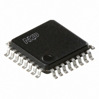
TDA8020HL/C2,118 NXP Semiconductors, TDA8020HL/C2,118 Datasheet - Page 13

TDA8020HL/C2,118
Manufacturer Part Number
TDA8020HL/C2,118
Description
IC SMART CARD INTERFACE 32LQFP
Manufacturer
NXP Semiconductors
Type
Interfacer
Datasheet
1.TDA8020HLC2118.pdf
(28 pages)
Specifications of TDA8020HL/C2,118
Package / Case
32-LQFP
Voltage - Supply
2.7 V ~ 6.5 V
Mounting Type
Surface Mount
Maximum Operating Temperature
+ 85 C
Minimum Operating Temperature
- 40 C
Mounting Style
SMD/SMT
Lead Free Status / RoHS Status
Lead free / RoHS Compliant
Number Of Drivers/receivers
-
Protocol
-
Lead Free Status / Rohs Status
Lead free / RoHS Compliant
Other names
568-3522-2
935272983118
TDA8020HL2BD-T
935272983118
TDA8020HL2BD-T
Available stocks
Company
Part Number
Manufacturer
Quantity
Price
Company:
Part Number:
TDA8020HL/C2,118
Manufacturer:
NXP Semiconductors
Quantity:
10 000
Part Number:
TDA8020HL/C2,118
Manufacturer:
NXP/恩智浦
Quantity:
20 000
Philips Semiconductors
Deactivation sequence
When the session is completed, the microcontroller resets bit START/STOP to logic 0 (t10). The circuit then executes an
automatic deactivation sequence (see Fig.5):
1. Card reset (RST falls LOW) (t11)
2. Clock is stopped (t12)
3. I/O falls to 0 V (t13)
4. V
5. The DC-to-DC converter is stopped (if both cards are inactive) and CLK, RST, V
6. The internal oscillator changes to its low frequency if both cards are inactive (t15).
t11 = t10 + T/64; t12 = t11 + T/2; t13 = t11 + T; t14 = t11 + 3T/2; t15 = t11 + 7T/2.
The deactivation time t
2003 Nov 06
handbook, full pagewidth
Dual IC card interface
to CGND (t15)
CC
falls to 0 V with a controlled slew rate (t14)
START/STOP
V UP
V CC
I/O
CLK
RST
de
is the time that V
t0 t1
CC
t2
needs to drop below 0.4 V from START/STOP to logic 0 (t10).
Fig.4 Activation sequence.
t3
13
t4
t5
CC
and I/O become low impedance
ATR
FCE837
TDA8020HL
Product specification


