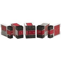
EM-T-7A BANNER ENGINEERING, EM-T-7A Datasheet

EM-T-7A
Specifications of EM-T-7A
Related parts for EM-T-7A
EM-T-7A Summary of contents
Page 1
... Primary Safety Device, such as an E-stop Safety Module or a two-hand-control module. Controlled by the safety outputs of the Primary Safety Device, the EM-T-7A Extension Module provides four redundant outputs. These outputs may be connected to control-reliable machine power interrupt circuits. Each of the four Extension Module outputs is a series connection of two forced-guided relay contacts (K1 and K2 in Figure 3) ...
Page 2
... Also, request a type “C” standard for your specific machinery. EN 418 “Safety of Machinery – Emergency Stop Equipment Functional Aspects, Principles for Design” Available from: 2 page Model EM-T-7A Safety Director AMT – The Association for Manufacturing Technology 7901 Westpark Drive McLean, VA 22101-4269 Tel.: 703-827-5266 National Fire Protection Association 1 Batterymarch Park, P ...
Page 3
... Figure 1. EM-T-7A status indicators Banner Engineering Corp. • Minneapolis, U.S.A. Website: http://www.baneng.com • Tel: 888.373.6767 Extension Module – Model EM-T-7A Specifications Each channel is a series connection of two forced-guided (positive-guided) relay contacts – AgNi, gold-flashed Maximum voltage: 250V ac/dc Maximum current ac/dc ...
Page 4
... Extension Module – Primary Safety Device Requirements Model EM-T-7A Extension Module is driven by one or two safety output channels of a Primary Safety Device. The design of the Primary Safety Device must meet OSHA and ANSI control reliability requirements. The EM-T-7A must be used ONLY with Primary Safety Devices which have a dedicated input for feedback monitor contacts (see hookup diagrams) ...
Page 5
... MSC4 * *Arc Suppressors (See Warning) Figure 3. Generalized EM-T-7A Hookup for One-Channel Control One-Channel Control (Figure 3) One-channel control affords simplicity of wiring. However, one-channel wiring requires eliminating the possibility of an unsafe failure of the control wires (which connect the output of the Primary Safety Device to the input of the Extension Module). One of the ways to reduce the probability of such failure is to locate the Primary Safety Device adjacent to the Extension Module in the same enclosure ...
Page 6
... MSC4 *Arc Suppressors * (See Warning) Figure 4. Generalized EM-T-7A Hookup for Two-Channel Control Two-Channel Control (Figure 4) Two-channel control allows the Primary Safety Device to detect an unsafe failure of the control wires. Two-channel control should be used whenever unsafe failure of the control wires cannot be eliminated. The outputs of the Primary Safety Device must each be normally open, forced-guided contacts from redundant safety relays ...
Page 7
... MSC Monitoring circuit to detect unsafe failures within the master stop control elements. This monitoring extends the safe switching point of the Primary Safety Device and the EM-T-7A Extension Module to the MSC elements. For this monitoring to be effective required that a minimum of two redundant MSCs control each hazard. This is to detect the unsafe failure of one MSC (e ...
Page 8
... Primary Safety Device controlling this Extension Module. Repairs Do not attempt any repairs to the EM-T-7A Extension Module. It contains no field- replaceable components. Return the Extension Module to the factory for warranty repair or replacement ever becomes necessary to return an Extension Module to the factory, please do ...


