EM-T-7A BANNER ENGINEERING, EM-T-7A Datasheet - Page 7
EM-T-7A
Manufacturer Part Number
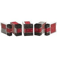
EM-T-7A
Description
Extension Module; Relay; Red LED; 24; DIN Rail; UL listed
Manufacturer
BANNER ENGINEERING
Specifications of EM-T-7A
Light Source
Red LED
Mounting
DIN Rail
Output Type
Relay
Standards
UL listed
Voltage, Supply
24 VAC⁄VDC
Coil Voltage Vdc Nom
24V
Contact Current Max
6A
Contact Voltage Ac Nom
250V
Contact Voltage Dc Nom
250V
Contact Configuration
DPDT-NO
No. Of Poles
2
Relay Mounting
DIN Rail
External Height
84mm
Lead Free Status / Rohs Status
RoHS Exempt Product


Before performing the initial checkout
procedure, make certain all power is
disconnected from the machine to be
controlled. Dangerous voltages may be
present along the Extension Module
wiring barriers whenever power to the
machine control elements is ON.
Exercise extreme caution whenever
machine control power is or may be
present.
extends the safe switching point of the Primary Safety Device and the EM-T-7A Extension Module to the MSC elements. For this
monitoring to be effective, it is required that a minimum of two redundant MSCs control each hazard. This is to detect the unsafe failure
of one MSC (e.g. a welded contact), while stopping the hazard and preventing a successive machine cycle with the second MSC.
If the MSCs are the last electrically controlled device generating the hazard (i.e. not relays or contactors) and do not have forced-
guided, captive contacts to monitor, then the customer must ensure that failure or fault of any single component of the MSCs will not
result in a hazardous situation and will prevent a successive machine cycle.
NOTE: MSC Monitoring is also called External Device Monitoring (EDM), MPCE Feedback, and relay backchecking.
Banner Engineering Corp. • Minneapolis, U.S.A.
Website: http://www.baneng.com • Tel: 888.373.6767
!
WARNING . . .
All Master Stop Control elements (MSCs), such as control relays, must be of forced-guided, captive contact design to
allow the MSC Monitoring circuit to detect unsafe failures within the master stop control elements. This monitoring
CAUTION . . .
Disconnect Power Prior to
Checkout
MSC Monitoring
To satisfy the requirements of control reliability, all MSCs must offer at least one normally
closed forced-guided monitor contact. One normally closed monitor contact from each
MSC is wired in series to the monitoring contact feedback input of the Primary Safety
Device, as shown in Figures 3 and 4. In operation, if one of the switching contacts of any
MSC fails in the shorted condition, the associated monitor contact will remain open. As a
result, it will not be possible to reset the Primary Safety Device.
Many types of mechanisms are used to arrest dangerous machine motion. Examples
include mechanical braking systems, clutch mechanisms, and combinations of brakes
and clutches. Additionally, control of the arresting scheme may be hydraulic or
pneumatic. As a result, an MSC may be one of several control types, including a wide
variety of contactors and electromechanical valves. If your machine documentation
leaves any doubt about the proper connection points for the Extension Module output
contacts, do not make any connections. Contact the machine builder for clarification
regarding connection to the MSCs.
NOTE: The Extension Module can only be used safely when its operation is controlled
Checkout procedure:
1) Remove the power controlling and switched by the machine control elements (see
2) Verify that the Primary Safety Device which will be controlling the Extension
3) Confirm proper connection of the Extension Module to the controlling Primary
4) Verify that all four Extension Module output contacts follow exactly the operation of
Initial Checkout Procedure
Caution at left).
Module is operating correctly, according to its product documentation and
manufacturer’s recommendations.
Safety Device according to the wiring diagram (see Figures 3 and 4).
the safety output contacts of the controlling Primary Safety Device, when the
Primary Safety Device is operated according to its product documentation and
manufacturer’s recommendations.
via an appropriate Primary Safety Device, connected to the Extension Module
according to wiring diagrams shown in Figure 3 or 4.
Extension Module –
Model EM-T-7A
page
7
Related parts for EM-T-7A
Image
Part Number
Description
Manufacturer
Datasheet
Request
R

Part Number:
Description:
Photoelectric Sensor
Manufacturer:
BANNER ENGINEERING
Datasheet:

Part Number:
Description:
Photoelectric Sensor
Manufacturer:
BANNER ENGINEERING
Datasheet:

Part Number:
Description:
LEDIR70XD4-XM-81039 MAX INTENS STROBE ONLY NO BANNER MARKS
Manufacturer:
BANNER ENGINEERING
Part Number:
Description:
M18SP6DL-72225 LABELED MOELLER NO BANNER MARKINGS BULK PACK
Manufacturer:
BANNER ENGINEERING
Part Number:
Description:
M18SP6DLQ-72226 LABLED MOELLER NO BANNER MARKINGS BULK PACK
Manufacturer:
BANNER ENGINEERING
Part Number:
Description:
M18SP6L-72223 LABELED MOELLER NO BANNER MARKINGS BULK PACK
Manufacturer:
BANNER ENGINEERING
Part Number:
Description:
M18SP6LQ-72224 LABELED MOELLER NO BANNER MARKINGS BULK PACK
Manufacturer:
BANNER ENGINEERING
Part Number:
Description:
P4D1-77908 P4 DRIVER GENERIC NO BANNER MARKINGS RESALE TO CUSTOMER
Manufacturer:
BANNER ENGINEERING
Part Number:
Description:
Photoelectric Sensor
Manufacturer:
BANNER ENGINEERING
Datasheet:

Part Number:
Description:
Programmable Indicator Light
Manufacturer:
BANNER ENGINEERING
Datasheet:
Part Number:
Description:
INDICATOR LED PANEL 50MM GRN/RED/YEL 30V
Manufacturer:
BANNER ENGINEERING
Datasheet:
Part Number:
Description:
Programmable Indicator Light
Manufacturer:
BANNER ENGINEERING
Datasheet: