328996 TE Connectivity, 328996 Datasheet
328996
Specifications of 328996


Related parts for 328996


328996 Summary of contents
Page 1
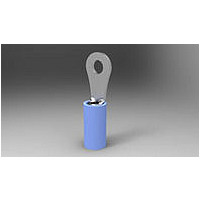
... The terminals are available with a variety of tongue lengths and configurations; and the terminals, splices, and end caps are available with various wire barrel lengths and diameters to accommodate different wire sizes, wire types, and combination of wire sizes ...
Page 2
... S Moved old Figure 6 to Figure 11 2.2. Customer Assistance Reference Product Base Part Number 51864 and Product Code 3022 are representative of PIDG terminals, splices, and end caps. Use of these numbers will identify the product line and expedite your inquiries through a service network established to help you obtain product and tooling information. Such information can be obtained through a local Representative or, after purchase, by calling PRODUCT INFORMATION at the number at the bottom of page 1 ...
Page 3
... AMPOMATOR* CLS IV+ Lead–Making Machines 356500– REQUIREMENTS 3.1. Limitation These terminals and end caps are suitable for 300 volts maximum, and the splices are suitable for 600 volts maximum. The terminals, splices, and end caps having the following insulation can withstand the following temperature range: nylon – ...
Page 4
... Contact PRODUCT INFORMATION at the number on page 1 for acceptable insulation diameter ranges [ Large sleeve terminal designed for Class I E Nuclear applications D For use with heavy–duty terminals having an insulation thickness of 1.02–1.27 [.040–.050] 4 PIDG Terminals, Splices, and End Caps WIRE STRIP LENGTH ...
Page 5
... This dot code can be used as a visual inspection to ensure that the correct wire size and crimping chamber were used. Crimp Inspection Using Micrometer or Comparator C Produced by Crescent Crimp Tooling F Produced by TETRA–CRIMP Tooling D PIDG Terminals, Splices, and End Caps Figure 3 Wire Barrel Crimp Profile and Location Figure 4 (Cont’d) 114-2157 5 ...
Page 6
... Yellow/Brown D For use with heavy duty terminals having an insulation thickness range of 1.02–1.27 [.040–.050]. The wire barrel crimp produced by the tooling (dies, heads, hand tools, pneumatic tools, or machines) must be either a confined crescent crimp which appears as a depressed oval shape or a flat rectangular crimp over the center of the wire barrel. The crimp must be evenly formed. Refer to Figures 4, 5, and 11. Crescent crimp tooling produces the crescent crimp, and TETRA– ...
Page 7
... See Figure 5. H. Wire Location 1. Terminals shall have the wire ends flush or extended slightly beyond the end of the wire barrel as shown in Figure 5. 2. Splices shall have the end of the wire located against the wire stop inside the center of the splice. ...
Page 8
... Hold Here About 76 in.] Crimped terminals, splices, or end caps should hold the wire conductor(s) firmly and have a pull–test tensile value meeting that specified in the table in Figure 7. Adjust tensile testing machine for head travel of 25.4 [1.0] per minute. Directly and gradually apply force for 1 minute. ...
Page 9
... Repair Damaged or defective terminal, splice, or end cap must not be used. If damage is evident, the terminal, splice, or end cap should be cut from the wire and replaced with a new one. Crimped terminals, splices, or end caps MUST NOT be re–terminated or re–used by removing the wire. ...
Page 10
... Hand tools consisting of a handle assembly with integral fixed jaws or dies and hand tools that accept various die assemblies are available for loose piece terminals, splices, or end caps. Both types feature a ratchet to ensure full crimping pressure is applied to the terminal, splice, or end cap. ...
Page 11
... D H For use with terminals having an insulation thickness range of 0.51–0.84 [.020–.033]. D For use with heavy duty terminals having an insulation thickness of 1.02–1.27 [.040 –.050]. Z For use with wire having a maximum insulation diameter of 7.62 [.300]. D PIDG Terminals, Splices, and End Caps ...
Page 12
... For use with terminals having an insulation thickness range of 0.51–0.84 [.020–.033]. D For use with heavy duty terminals having an insulation thickness of 1.02–1.27 [.040 –.050]. Z For use with wire having a maximum insulation diameter of 7.62 [.300]. Power Units C F Figure 10 (End) ...
Page 13
... VISUAL AID Figure 11 shows a typical application of PIDG terminals, splices, and end caps. This illustration should be used by production personnel to ensure a correctly applied terminal, splice, or end cap. Applications which DO NOT appear correct should be inspected using the information in the preceding pages of this specification and in the instructional material shipped with the product or tooling ...
Page 14
... Too Much Space Between Wire Conductor(s) and Wire Barrel Front Bellmouth on Top of Insulation Too Large PIDG Terminals, Splices, and End Caps PROPER CRIMP Crimp Centered on Wire Barrel Detail A Detail B (Insulation and Metal Sleeve Removed) Front Bellmouth on Top and Bottom of Wire Barrel ...