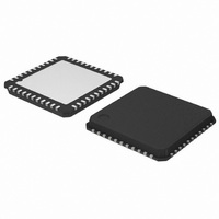
AMIS-49200-XTD ON Semiconductor, AMIS-49200-XTD Datasheet - Page 12

AMIS-49200-XTD
Manufacturer Part Number
AMIS-49200-XTD
Description
TXRX FIELDBUS MAU 44-LQFP
Manufacturer
ON Semiconductor
Type
Transceiverr
Specifications of AMIS-49200-XTD
Number Of Drivers/receivers
1/1
Protocol
MDS-MAU
Voltage - Supply
4.75 V ~ 6.2 V
Mounting Type
Surface Mount
Package / Case
44-LQFP
Logic Type
Fieldbus Media Access Unit
Logic Family
AMIS-49200
Input Level
CMOS
Supply Voltage (max)
6.2 V
Supply Voltage (min)
3 V
Maximum Operating Temperature
+ 85 C
Function
A transceiver chip for low speed FOUNDATION Fieldbus and Profibus PA devices
Minimum Operating Temperature
- 40 C
Mounting Style
SMD/SMT
Lead Free Status / RoHS Status
Lead free / RoHS Compliant
Other names
766-1019
Available stocks
Company
Part Number
Manufacturer
Quantity
Price
Company:
Part Number:
AMIS-49200-XTD
Manufacturer:
ON Semiconductor
Quantity:
31
Company:
Part Number:
AMIS-49200-XTD
Manufacturer:
ON Semiconductor
Quantity:
10 000
AMIS-492x0
The SHUNT pin is normally connected to V
Its value should be small enough to keep V
than 100Ω.).
Since the internal transistor can sink as much as 25mA, no additional circuit is necessary in most cases. Note that the drain current
must not exceed 25mA because no protection is implemented for the internal transistor. If you do not need the shunt regulator, you
should connect SHUNT and SHSETIN pins to GND and open SHSET pin. Then V
4.2.2. Series Regulator
The series regulator produces a regulated voltage at the V
amplifier will regulate the input voltage at SRSETIN pin to equal V
equal to V
Figure 5) of 5μF or larger capacity is necessary to stabilize this regulator. The capacitor is expected to have an ESR resistor for the
circuit to be stable. If the capacitor is low, a series resistor with the cap load will help stabilize the circuit).
The supply current must not exceed 20mA because no current limiting is applied to the internal transistor. You can increase V
up to 3.5V by dividing V
kept open. The drain-source voltage of the internal transistor must be larger or equal to 2V. If this condition is not satisfied, you may
need an external P-channel JFET to create the desired low voltage-drop regulator. The output voltage is determined by the following
equation.
4.2.3. Low Voltage Detectors
Low voltage detectors are included to monitor supply voltages and generate “power fail” signals. The low voltage alarms are detected
by sensing the voltage on pins SHSETIN and SRSETIN. These pins also provide feedback for the shunt and series regulators. If the
voltage on the SHSETIN pin is lower than the threshold, VTH9 (90 percent VREF), N_PFAIL1 goes low. Typically SHSETIN monitors
the analog rail voltage VCC. If the voltage on the SRSETIN pin is lower than the threshold, VTH9, N_PFAIL2 goes low. Typically
SRSETIN monitors the digital rail voltage VDD.
Both outputs are open drain, so a resistor will be required. If you do not use one of these pins, it should be connected to GND. You
can also add capacitors to delay these signals. In this case, sink current must not exceed the maximum value.
If you do not wish to use one of the low voltage detectors its corresponding output pin should be connected to GND.
REF
C
D
Supply
VDD
May
at pin SRSET. If you connect SRSET and SRSETIN pins, the series regulator supplies 3V at pin V
SRSET
16
13
VO
O
with an external network to supply the appropriate voltage to pin SRSETIN. In this case, pin SRSET must be
1.54Rsr
Rsr
20pF
Cc2
(Internal Configuration)
SRTR
Series Regulator
20mA (Max)
15
14
CC
DS
. It is possible to insert a resister between V
SRAO
40pF
Cfb1
(voltage between SHUNT pin and SGND pin) larger than 2.5V (i.e., resistor must be less
A7
Rev. 6 | Page 12 of 22 | www.onsemi.com
12
VO = VREF × (1 + R4/R5)
VCC
Figure 5: Series Regulator
VREF
SRSETIN
O
pin from V
REF
C
Supply
D
. An internal feedback signal is generated to produce a voltage
VDD
May
CC
. If you connect SRAO and SRTR pins together, the internal
R4
R5
N/C
SRSET
16
13
CC
VO
must be supplied from another source.
(External Configuration)
1.54Rsr
Rsr
20pF
Cc2
CC
Series Regulator
and SHUNT to measure the shunt current.
SRTR
20mA (Max)
15
14
SRAO
40pF
Cfb1
A7
O
. A capacitor (C
12
VCC
VREF
SRSETIN
O
voltage
D
in


