AD53040KRP Analog Devices Inc, AD53040KRP Datasheet - Page 2
AD53040KRP
Manufacturer Part Number
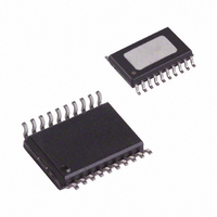
AD53040KRP
Description
IC PIN DRIVER W/INHIBIT 20-PSOP
Manufacturer
Analog Devices Inc
Type
Driverr
Datasheet
1.AD53040KRP.pdf
(7 pages)
Specifications of AD53040KRP
Rohs Status
RoHS non-compliant
Number Of Drivers/receivers
1/0
Voltage - Supply
12V
Mounting Type
Surface Mount
Package / Case
20-PowerSOP Exposed Top Pad
Supply Voltage Max
19V
No. Of Outputs
1
Output Voltage
8V
Output Current
30mA
Driver Case Style
SOP
Msl
MSL 1 - Unlimited
Peak Reflow Compatible (260 C)
No
Device Type
Pin
Termination Type
SMD
No. Of Pins
20
Rohs Compliant
No
Protocol
-
Lead Free Status / RoHS Status
Contains lead / RoHS non-compliant
Available stocks
Company
Part Number
Manufacturer
Quantity
Price

Part Number:
AD53040KRPZ
Manufacturer:
ADI/亚德诺
Quantity:
20 000


AD53040–SPECIFICATIONS
3% unless otherwise noted. All temperature coefficients are measured at T
V
Parameter
DIFFERENTIAL INPUT CHARACTERISTICS
REFERENCE INPUTS
OUTPUT CHARACTERISTICS
DYNAMIC PERFORMANCE, DRIVE
CC
Input Swing (Data to DATA, INH to INH)
Max (DATA, DATA) to Min (INH, INH)
Max (INH, INH) to Min (Data, DATA)
Bias Current
Bias Currents
Logic High Range
Logic Low Range
Amplitude (V
Absolute Accuracy
Offset TC, V
Output Resistance
Output Leakage
Dynamic Current Limit
Static Current Limit
PSRR, Drive Mode
(V
and V
V
V
V
V
H
Propagation Delay Time
Propagation Delay TC
Delay Matching, Edge to Edge
Rise and Fall Time
Rise and Fall Time TC
Overshoot, Undershoot and Preshoot
Settling Time
H
H
L
L
and V
1 V Swing
3 V Swing
5 V Swing
1 V Swing
3 V Swing
5 V Swing
to 15 mV
to 4 mV
Delay Change vs. Pulsewidth
Offset
Gain + Linearity Error
Offset
Gain + Linearity Error
HDCPL
L
)
and between V
H
H
or V
and V
L
L
)
EE
and V
LDCPL
.)
Min
–50
–2
–3
0.1
–100
–100
45
–1.0
(All specifications are at T
Typ
ECL
0.5
47
150
35
1.5
2
100
0.8
1.7
2.4
40
8
50
10
0.3 5
0.3 5
65
1
2
3
(1% +50 mV)
–2–
J
Max
2
2
+50
+8
+5
9
+100 mV
+100 mV
49
+1.0
= +75 C–95 C). (A 39 nF capacitor must be connected between
Units
Volts
Volts
Volts
Volts
Volts
% of V
% of V
mV/ C
mA
mA
dB
ns
ps/ C
ps
ns
ns
ns
ps/ C
ps/ C
ps/ C
% of Step + mV
ns
ps
A
A
A
s
J
= +85 C
H
L
+ mV
+ mV
5 C, +V
Test Conditions
V
V
DATA = H, V
V
V
DATA = L, V
V
V
DATA = H, V
DATA = H, V
DATA = L, V
DATA = L, V
V
DATA = H, V
I
V
C
Output to –3 V, V
DATA = H and Output to +8 V, V
V
V
Measured at 50%, V
V
Measured at 50%, V
V
Measured at 50%, V
V
Measured 20%–80%, V
Measured 10%–90%, V
Measured 10%–90%, V
Measured 20%–80%, V
Measured 10%–90%, V
Measured 10%–90%, V
a. V
b. V
c. V
V
V
V
Pulsewidth = 2.5 ns/7.5 ns, 30 ns/100 ns
OUT
IN
L
L
L
L
L
L
OUT
L
S
L
L
L
L
L
L
BYP
, V
, V
= V
= –3 V (V
= –1 V (V
= –0.05 V, V
= –2 V, V
= –3 V, DATA = L
= –400 mV
= –400 mV
= –400 mV
= 0 V, V
= 0 V, V
= 0 V, V
= –2 V, 0.0 V
L
L
L
= 30 mA
H
H
= 39 nF, V
, V
, V
= –3 V to +8 V
, V
S
S
= 5 V
= 0 V, +5 V and –3 V, 0 V
H
= +12 V
H
H
= 0.0 V, 1.0 V
= 0.0 V, 5.0 V
3%
= 0.0 V, 3.0 V
H
H
H
H
H
H
= 0.5 V
= 0.5 V
= 2 V,
L
L
L
H
H
H
H
= +7 V
= –2 V to +6 V)
= +6 V to +8 V)
= –3 V to +5 V, V
= –3 V to +5 V, V
= –3 V to +5 V, V
H
= –2 V to +8 V
= –2 V to +8 V, V
= –2 V to +8 V, V
= +3 V, V
H
= +0.05 V and
H
= +7 V, V
= +8 V, V
H
H
H
3%, –V
= +400 mV,
= +400 mV,
= +400 mV,
L
L
L
L
L
L
= 0 V, V
= 0 V, V
= 0 V, V
= 0 V, V
= 0 V, V
= 0 V, V
L
S
= 0 V,
L
= –7 V
= –2 V
L
= –1 V,
H
H
H
H
H
H
H
H
H
H
REV. B
L
L
= +6 V,
= +6 V
= +6 V
= +6 V
= 1 V
= 3 V
= 5 V
= 1 V
= 3 V
= 5 V
= –3 V
= –3 V
Related parts for AD53040KRP
Image
Part Number
Description
Manufacturer
Datasheet
Request
R

Part Number:
Description:
GSM Baseband Processing Chipset
Manufacturer:
AD [Analog Devices]
Datasheet:

Part Number:
Description:
±1.7g Dual-Axis IMEMS Accelerometer Evaluation Board
Manufacturer:
Analog Devices Inc
Datasheet:

Part Number:
Description:
Inertial Sensor Evaluation System
Manufacturer:
Analog Devices Inc
Datasheet:
Part Number:
Description:
Manufacturer:
Analog Devices Inc
Datasheet:
Part Number:
Description:
Manufacturer:
Analog Devices Inc
Datasheet:
Part Number:
Description:
Manufacturer:
Analog Devices Inc
Datasheet:
Part Number:
Description:
Manufacturer:
Analog Devices Inc
Datasheet:
Part Number:
Description:
Manufacturer:
Analog Devices Inc
Datasheet:
Part Number:
Description:
Manufacturer:
Analog Devices Inc
Datasheet:
Part Number:
Description:
Manufacturer:
Analog Devices Inc
Datasheet:
Part Number:
Description:
Manufacturer:
Analog Devices Inc
Datasheet:
Part Number:
Description:
Manufacturer:
Analog Devices Inc
Datasheet:
Part Number:
Description:
Manufacturer:
Analog Devices Inc
Datasheet: