Si8230-A-IS Silicon Laboratories Inc, Si8230-A-IS Datasheet - Page 29

Si8230-A-IS
Manufacturer Part Number
Si8230-A-IS
Description
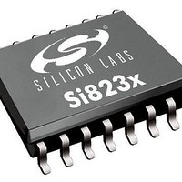
MOSFET & Power Driver ICs 0.5A HS/LS ISOdriver Dual Input
Manufacturer
Silicon Laboratories Inc
Type
High and Low Sider
Datasheet
1.SI8234BD-C-IS.pdf
(52 pages)
Specifications of Si8230-A-IS
Rise Time
12 ns
Fall Time
12 ns
Propagation Delay Time
50 ns
Supply Voltage (max)
24 V
Supply Voltage (min)
10 V
Supply Current
11 mA
Maximum Operating Temperature
+ 125 C
Mounting Style
SMD/SMT
Package / Case
SOIC-16
Bridge Type
Half Bridge
Minimum Operating Temperature
- 40 C
Number Of Drivers
2
Number Of Outputs
2
Output Current
0.5 A
Lead Free Status / Rohs Status
Lead free / RoHS Compliant
4.2. Dual Driver
Figure 43 shows the Si823x configured as a dual driver. Note that the drain voltages of Q1 and Q2 can be
referenced to a common ground or to different grounds with as much as 1500 V dc between them.
Because each output driver resides on its own die, the relative voltage polarities of VOA and VOB can reverse
without damaging the driver. That is, the voltage at VOA can be higher or lower than that of VOB by VDD without
damaging the driver. Therefore, a dual driver in a low-side high side/low side drive application can use either VOA
or VOB as the high side driver. Similarly, a dual driver can operate as a dual low-side or dual high-side driver and is
unaffected by static or dynamic voltage polarity changes.
4.3. Dual Driver with Thermally Enhanced Package (Si8236)
The thermal pad of the Si8236 must be connected to a heat spreader to lower thermal resistance. Generally, the
larger the thermal shield’s area, the lower the thermal resistance. It is recommended that thermal vias also be used
to add mass to the shield. Vias generally have much more mass than the shield alone and consume less space,
thus reducing thermal resistance more effectively. While the heat spreader is not generally a circuit ground, it is a
good reference plane for the Si8236 and is also useful as a shield layer for EMI reduction.
With a 10mm
was measured at 50 °C/W. This is a significant improvement over the Si835 which does not include a thermal pad.
The Si8235’s thermal resistance was measured at 105 °C /W.
2
thermal plane on the outer layers (including 20 thermal vias), the thermal impedance of the Si8236
CONTROLLER
Figure 43. Si8235 in a Dual Driver Application
PH2
PH1
I/O
10 µF
C1
VDDI
VDDI
VIA
VIB
GNDI
DISABLE
Rev. 1.1
Si8235/6
GNDB
VDDA
GNDA
VDDB
VOA
VOB
VDDA
VDDB
10 µF
10 µF
C2
C3
Q1
Q2
Si823x
29


