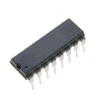
MC44603P ON Semiconductor, MC44603P Datasheet - Page 16

MC44603P
Manufacturer Part Number
MC44603P
Description
Other Power Management Voltage/Current PWM
Manufacturer
ON Semiconductor
Type
PWM Mode Controllerr
Datasheet
1.MC44603DWR2.pdf
(24 pages)
Specifications of MC44603P
Input Voltage Range
18 V
Mounting Style
Through Hole
Package / Case
PDIP-16
Lead Free Status / Rohs Status
Lead free / RoHS Compliant
Available stocks
Company
Part Number
Manufacturer
Quantity
Price
Part Number:
MC44603P
Manufacturer:
MOTOROLA/摩托罗拉
Quantity:
20 000
Company:
Part Number:
MC44603P2
Manufacturer:
ON
Quantity:
9 800
(Pin 13). Thus, the error signal controls the peak inductor
current on a cycle−by−cycle basis. The Current Sense
Comparator PWM Latch ensures that only a single pulse
appears at the Source Output during the appropriate
oscillator cycle.
the ground referenced sense resistor R
power switch Q1.
(Pin 7) and compared to a level derived from the Error Amp
output. The peak inductor current under normal operating
conditions is controlled by the voltage at Pin 13 where:
clamped to 1.0 V. Therefore, the maximum peak switch
current is:
Series gate resistor, R2, will dampen any high frequency
oscillations caused by the MOSFET input capacitance and
any series wiring inductance in the gate−source circuit.
Diode D is required if the negative current into the output
drive pin exceeds 15 mA.
Oscillator
can work either in free mode or in synchronization mode. In
this second mode, the oscillator stops in the low state and
waits for a demagnetization or a synchronization pulse to
start a new charging cycle.
•
about 1.6 V and 3.6 V.
external capacitor C
sources = I
connected to the charging current source (0.4 I
The inductor current is converted to a voltage by inserting
This voltage is monitored by the Current Sense Input
The Current Sense Comparator threshold is internally
Thermal
Protection
The oscillator is a very accurate sawtooth generator that
In the steady state, the oscillator voltage varies between
The sawtooth is obtained by charging and discharging an
The Sawtooth Generation:
Current Sense
V
Comparator
Demag Out
V
OSC prot
charge
S
R
R
PWM
Latch
Figure 34. Output Totem Pole
Q
I pk [
I pk(max) [
and I
UVLO
T
(Pin 10), using two distinct current
discharge
V (Pin 13) – 1.4 V
Substrate
1.0 V
3 R S
. In fact, C
R S
14
V
Current
Sense
3
7
C
1N5819
D
S
R2
in series with the
T
C
is permanently
R3
ref
R
) and so,
V
R
in
S
http://onsemi.com
Q1
16
the discharge current source has to be higher than the
charge current to be able to decrease the C
to Figure 36).
normal working and (0.4 I
compare the C
peak reference (3.6 V) values. A latch (L
the oscillator state.
can exist. This phase can be produced when, at the end of the
discharge phase, the oscillator has to wait for a
synchronization or demagnetization pulse before restarting.
During this delay, the C
oscillator valley value (]1.6 V). So, a third regulated
current source I
to C
source that permanently supplies C
allowed only during the oscillator capacitor charge.
C
This condition is performed, its value being (2.0 I
Two comparators are used to generate the sawtooth. They
In addition to the charge and discharge cycles, a third state
The maximum duty cycle is 80%. Indeed, the on−time is
T
10
T
C
in order to perfectly compensate the (0.4 I
10
T
Figure 36. Simplified Block Oscillator
1.0 V
1.6 V
3.6 V
V
ref
1
T
I
0.4 I
Regul
V
Charge
0 1
voltage to the oscillator valley (1.6 V) and
ref
0
0.4 I
ref
I
Figure 35. Oscillator
Regul
I
C
Discharge
C
C
C
controlled by C
OSC High
VOS prot
OSC Low
OSC Regul
ref
0: Discharge Phase
1: Charge Phase
T
voltage must remain equal to the
ref
+ 0.5 I
C
Discharge
T
< 1.6 V
Disch
R
S
1.6 V
Q
T
F Stby
.
OSC Regul
V
OSC prot
L
R
S
I
Regul
OSC
in standby mode).
disch
Q
T
voltage (refer
C
, is connected
OSC Regul
) memorizes
0
ref
I
1
Discharge
) current
Synchro
V
Out
Demag
ref
V
OSC
) in


