LZP-00WW00 LedEngin, LZP-00WW00 Datasheet - Page 6
LZP-00WW00
Manufacturer Part Number
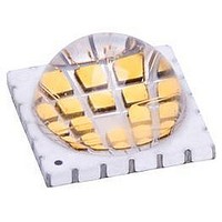
LZP-00WW00
Description
LED High Power (> 0.5 Watts) Warm White 90 Watts
Manufacturer
LedEngin
Datasheet
1.LZP-00WW00.pdf
(13 pages)
Specifications of LZP-00WW00
Rohs Compliant
Yes
Led Color
Warm White
Luminous Flux @ Test
3300lm
Cct
3100K
Forward Current @ Test
1A
Forward Current If Max
1.5A
Forward Voltage @ Test
21.9V
Power Dissipation Pd
90W
Viewing Angle
110°
Lead Free Status / Rohs Status
Details


Notes for Table 5:
1.
2:
3.
4.
5.
Notes for Table 6:
1.
2.
Notes for Table 7:
1.
Maximum DC forward current (per die) is determined by the overall thermal resistance and ambient temperature.
Follow the curves in Figure 10 for current de-rating.
Pulse forward current conditions: Pulse Width ≤ 10msec and Duty cycle ≤ 10%.
LEDs are not designed to be reverse biased.
Solder conditions per JEDEC 020D. See Reflow Soldering Profile Figure 5.
LedEngin recommends taking reasonable precautions towards possible ESD damages and handling the LZP-00WW00
in an electrostatic protected area (EPA). An EPA may be adequately protected by ESD controls as outlined in
ANSI/ESD S6.1.
Luminous flux typical value is for all 24 LED dies operating at rated current.
Viewing Angle is the off-axis angle from emitter centerline where the luminous intensity is ½ of the peak value.
Forward Voltage is measured for a single string of 6 dies connected in series. The LED is configured with 4 Channels of
6 dies in series each.
DC Forward Current at T
DC Forward Current at T
Peak Pulsed Forward Current
Forward Voltage (@ I
Soldering Temperature
Allowable Reflow Cycles
Luminous Efficacy (@ I
Forward Voltage (@ I
Luminous Flux (@ I
Junction Temperature
Luminous Flux (@ I
Storage Temperature
Correlated Color Temperature
Color Rendering Index (CRI)
ESD Sensitivity
Reverse Voltage
Chromaticity Coordinates
Temperature Coefficient
Parameter
of Forward Voltage
Thermal Resistance
(Junction to Case)
Viewing Angle
Parameter
Parameter
Electrical Characteristics @ T
Optical Characteristics @ T
jmax
jmax
[5]
F
Absolute Maximum Ratings
F
F
=135°C
=150°C
= 1000mA)
F
= 700mA)
= 1000mA)
[4]
= 700mA)
F
[2]
= 350mA)
[2]
[1]
[1]
[1]
[1]
[1]
[1]
[1]
Table 5:
Table 6:
Table 7:
Symbol
6
T
T
Symbol
Symbol
ΔV
I
V
T
R
I
I
FP
stg
F
F
sol
RΘ
2Θ
R
J
CCT
a
Φ
Φ
x,y
V
V
F
/ R9
/ΔT
F
F
V
V
1/2
J-C
J
Class 3B JESD22-A114-D
C
21.0 /Channel
21.9 /Channel
0.430, 0.402
C
= 25°C
Typical
Typical
83 / 15
= 25°C
> 8,000 V HBM
2500
3300
3100
-33.6
1500 /Channel
110
0.6
70
See Note 3
-40 ~ +150
Value
1200
1000
150
260
6
LZP-00WW00 (R.2.1 - 2011)
Degrees
mV/°C
lm/W
°C/W
Unit
Unit
lm
lm
K
V
V
Unit
mA
mA
mA
°C
°C
°C
V
Related parts for LZP-00WW00
Image
Part Number
Description
Manufacturer
Datasheet
Request
R

Part Number:
Description:
LED High Power (> 0.5 Watts) Warm White 90 Watts
Manufacturer:
LedEngin
Datasheet:
Part Number:
Description:
LED High Power (> 0.5 Watts) Neutral Wht 90 Watts
Manufacturer:
LedEngin
Datasheet:
Part Number:
Description:
LED High Power (> 0.5 Watts) Cool White 90 Watts
Manufacturer:
LedEngin
Datasheet:

Part Number:
Description:
25 Die Cool White (5500K) LED Emitter On MCPCB
Manufacturer:
LedEngin
Datasheet:

Part Number:
Description:
LED High Power (> 0.5 Watts) Cool White 90 Watts
Manufacturer:
LedEngin
Datasheet:
Part Number:
Description:
LED High Power (> 0.5 Watts) Ultraviolet 90 Watts
Manufacturer:
LedEngin
Datasheet:
Part Number:
Description:
LED High Power (> 0.5 Watts) Ultraviolet 90 Watts
Manufacturer:
LedEngin
Datasheet:
Part Number:
Description:
LED High Power (> 0.5 Watts) Neutral Wht 90 Watts
Manufacturer:
LedEngin
Datasheet:
Part Number:
Description:
LED High Power (> 0.5 Watts) Ultraviolet 90 Watts
Manufacturer:
LedEngin
Datasheet:
Part Number:
Description:
LED High Power (> 0.5 Watts) Ultraviolet 90 Watts
Manufacturer:
LedEngin
Datasheet:

Part Number:
Description:
LED High Power (> 0.5 Watts) Cool White 40 Watts 12 Die 2x6 Pattern
Manufacturer:
LedEngin
Datasheet:

Part Number:
Description:
LED High Power (> 0.5 Watts) Ultraviolet 5 Watt 365 nm
Manufacturer:
LedEngin
Datasheet:
Part Number:
Description:
LED High Power (> 0.5 Watts) Neutral Wht 40 Watts 12 Die 2x6 Pattern
Manufacturer:
LedEngin
Datasheet:

Part Number:
Description:
LED High Power (> 0.5 Watts) RGBA 40 Watts
Manufacturer:
LedEngin
Datasheet:

Part Number:
Description:
LED High Power (> 0.5 Watts) Cool White 40 Watts
Manufacturer:
LedEngin
Datasheet: