CDB1601-120W-Z Cirrus Logic Inc, CDB1601-120W-Z Datasheet - Page 9
CDB1601-120W-Z
Manufacturer Part Number
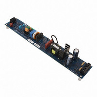
CDB1601-120W-Z
Description
High-efficiency PFC Demo. Board
Manufacturer
Cirrus Logic Inc
Series
-r
Datasheets
1.CDB150X-01-Z.pdf
(2 pages)
2.CDB1601-120W-Z.pdf
(24 pages)
3.CDB1601-120W-Z.pdf
(16 pages)
Specifications of CDB1601-120W-Z
Silicon Manufacturer
Cirrus Logic
Kit Application Type
Power Management
Application Sub Type
Power Factor Correction (PFC)
Kit Contents
Board, Datasheet
Design Resources
CS150x/160x PCB Layout Guidelines
Featured Product
CS1501/CS1601 Power Factor Correction IC Controllers
Main Purpose
Power Management, Power Factor Correction
Embedded
No
Utilized Ic / Part
CS1601
Primary Attributes
108 ~ 305 VAC Input, 460V 120W Output
Secondary Attributes
Ballast Control, Up to 2 T5 Lamps
Lead Free Status / Rohs Status
Lead free / RoHS Compliant


5. GENERAL DESCRIPTION
The CS1601 offers numerous features, options, and
functional capabilities to the electronic product lighting
designer. This digital PFC control IC is designed to replace
legacy analog PFC controllers with minimal design effort.
5.1 PFC Operation
One key feature of the CS1601 is its operating frequency
profile. Figure 11 illustrates how the frequency varies over half
cycle of the line voltage in steady-state operation. When
power is first applied to the CS1601, it examines the line
voltage and adapts its operating frequency to the line voltage
as shown in Figure 11. The operating frequency is varied from
the peak to the trough of the AC input. During startup, the
control algorithm generates maximum power while operating
in critical conduction mode (CRM), providing an approximate
square-wave current envelop within every half-line cycle.
Figure 12 illustrates how the operating frequency of CS1601
(as a percentage of maximum frequency) changes with output
power and the peak of the line voltage.
Figure 12. CS1601 Max Switching Freq vs. Output Power
DS931PP6
Figure 11. Switching Frequency vs. Phase Angle
120
100
80
60
40
20
40
20
70
60
48
0
0
0
5
Switching Freq. (% of Max.)
Rectified Line Voltage Phase (Deg.)
20
Vin <182 VAC (Input Voltage 108 –305 VAC , V
Vin <158 VAC (Input Voltage 90 –264 VAC, V
Vin >156 VAC (Input Voltage 108 – 305 VAC, V
Vin >136 VAC (Input Voltage 90 –264 VAC , V
45
Line Voltage (% of Max.)
40
% P
O max
90
60
135
link
link
80
link
link
= 400 V)
= 400 V)
= 460V)
= 460V)
100
180
Figure 13 illustrates how the operating frequency of CS1601H
changes with output power and the peak of the line voltage.
Figure 13. CS1601H Max Switching Freq vs.Output Power
When P
(Refer to
The CS1601 is designed to function as a DCM controller.
However, during peak periods, the controller may interchange
control methods and operate in a quasi-critical-conduction
mode (quasi-CRM) at low line. For example, at 108VAC main
input under full load, the PFC controller will function as a
quasi-CRM controller at the peak of the AC line cycle, as
shown in Figure 14.
The zero-current detection (ZCD) of the boost inductor is
achieved using an auxiliary winding. When the stored energy
of the inductor is fully released to the output, the voltage on the
ZCD pin decreases, triggering a new switching cycle. This
quasi-resonant switching allows the active switch to be turned
on with near-zero inductor current, resulting in a nearly
lossless switch event. This minimizes turn-on losses and EMI
noise created by the switching cycle. Power factor correction
control is achieved during light load by using on-time
modulation.
Figure 14. DCM and quasi-CRM Operation with CS1601
O
DCM
Burst Mode
100
falls below 5%, the CS1601 changes to Burst Mode.
75
50
25
0
5
Quasi CRM
20
Vin< 182 VAC (Input Voltage 108 –305 VAC, V
Vin< 158 VAC (Input Voltage 90– 264 VAC, V
Vin> 156 VAC (Input Voltage 108 –305 VAC , V
Vin >136 VAC (Input Voltage 90 –264 VAC , V
section for more information.)
I
LB
40
% P
DCM
O max
60
Quasi CRM
80
link
link
link
link
= 400V)
= 400V)
= 460 V)
= 460V)
CS1601
DCM
100
I
AC
t [ms]
9
Related parts for CDB1601-120W-Z
Image
Part Number
Description
Manufacturer
Datasheet
Request
R

Part Number:
Description:
Development Kit
Manufacturer:
Cirrus Logic Inc
Datasheet:
Part Number:
Description:
Development Kit
Manufacturer:
Cirrus Logic Inc
Datasheet:


Part Number:
Description:
High-efficiency PFC + Fluorescent Lamp Driver Reference Design
Manufacturer:
Cirrus Logic Inc
Datasheet:
Part Number:
Description:
Development Kit
Manufacturer:
Cirrus Logic Inc
Datasheet:
Part Number:
Description:
Development Kit
Manufacturer:
Cirrus Logic Inc
Datasheet:

Part Number:
Description:
Development Kit
Manufacturer:
Cirrus Logic Inc
Datasheet:
Part Number:
Description:
Development Kit
Manufacturer:
Cirrus Logic Inc
Datasheet:
Part Number:
Description:
Development Kit
Manufacturer:
Cirrus Logic Inc
Datasheet:
Part Number:
Description:
Development Kit
Manufacturer:
Cirrus Logic Inc
Datasheet:

Part Number:
Description:
EVALUATION BOARD FOR CS8427
Manufacturer:
Cirrus Logic Inc
Datasheet:

Part Number:
Description:
BOARD EVAL FOR CS8416 RCVR
Manufacturer:
Cirrus Logic Inc
Datasheet:

Part Number:
Description:
EVALUATION BOARD FOR CS8420
Manufacturer:
Cirrus Logic Inc
Datasheet:

Part Number:
Description:
KIT DEVELOPMENT EP9315 ARM9
Manufacturer:
Cirrus Logic Inc
Datasheet:

Part Number:
Description:
KIT DEVELOPMENT EP9302 ARM9
Manufacturer:
Cirrus Logic Inc
Datasheet: