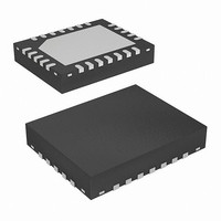
EL1508CL Intersil, EL1508CL Datasheet - Page 15

EL1508CL
Manufacturer Part Number
EL1508CL
Description
IC LINE DRIVER ADSL 24-QFN
Manufacturer
Intersil
Type
Driverr
Datasheet
1.EL1508CL.pdf
(18 pages)
Specifications of EL1508CL
Number Of Drivers/receivers
1/0
Voltage - Supply
5 V ~ 12 V
Mounting Type
Surface Mount
Package / Case
24-VQFN Exposed Pad, 24-HVQFN, 24-SQFN, 24-DHVQFN
Lead Free Status / RoHS Status
Contains lead / RoHS non-compliant
Protocol
-
Available stocks
Company
Part Number
Manufacturer
Quantity
Price
Company:
Part Number:
EL1508CL
Manufacturer:
ELANTEC
Quantity:
18 888
Company:
Part Number:
EL1508CL
Manufacturer:
Elantec
Quantity:
289
Company:
Part Number:
EL1508CL-AAA
Manufacturer:
EL
Quantity:
336
Part Number:
EL1508CLZ
Manufacturer:
INTERSIL
Quantity:
20 000
EL1508CM PCB Layout Considerations
The 20 Ld SOIC (0.300") Power Package is designed so that
heat may be conducted away from the device in an efficient
manner. To disperse this heat, the center four leads on either
side of the package are internally fused to the mounting
platform of the die. Heat flows through the leads into the
circuit board copper, then spreads and convects to air. Thus,
the ground plane on the component side of the board
becomes the heatsink. This has proven to be a very effective
technique, but several aspects of board layout should be
noted. First, the heat should not be shunted to internal
copper layers of the board nor backside foil, since the
feedthroughs and fiberglass of the board are not very
thermally conductive. To obtain the best thermal resistance
of the mounted part, θ
should have as much area as possible and be as thick as
practical. If possible, the solder mask should be cut away
from the EL1508 to improve thermal resistance. Finally,
metal heatsinks can be placed against the board close to the
part to draw heat toward the chassis. The graph below
shows various θ
copper foil areas.
INTERNAL GROUND PLANE (16 Ld SO)
JA
s for the 20 Ld SOIC mounted on different
JA
TOP (16 Ld SO)
, the topside copper ground plane
15
EL1508
Power Control Function
The EL1508 contains two forms of power control operation.
Two digital inputs, C
supply current of the EL1508 drive amplifiers. As the supply
current is reduced, the EL1508 will start to exhibit slightly
higher levels of distortion and the frequency response will be
limited. The 4 power modes of the EL1508 are set up as
shown in the following table:
Another method for controlling the power consumption of the
EL1508 is to connect a resistor from the I
When the I
current per channel is as per the specifications table on page
2. When a resistor is inserted, the supply current is scaled
according to the “R
Curves section.
Both methods of power control can be used simultaneously.
In this case, positive and negative supply currents (per amp)
are given by the equations below:
Output Loading
While the drive amplifiers can output in excess of 500mA
transiently, the internal metallization is not designed to carry
more than 100mA of steady DC current and there is no
I
I
S
S
FIGURE 45. THERMAL RESISTANCE of 20 LD SO (0.300")
+
-
C
=
=
0
0
1
1
1
------------------------------------------------------
(
0.9mA
1
+
55
50
45
40
35
30
TABLE 1. POWER MODES OF THE EL1508
R
ADJ
0
12.4mA
SET
+
EL1508 vs BOARD COPPER AREA
C
------------------------------------------------------
(
0
1
0
1
AREA OF CIRCUIT BOARD HEAT SINK (in
pin is grounded (the normal state), the supply
1
0
÷
+
1574Ω
TOP FOIL ONLY-NO SOLDER MASK
R
SET
2
0
12.4mA
SET
I
2/3 I
1/3 I
Power-down
and C
S
TOP FOIL ONLY-WITH SOLDER MASK
full power mode
vs I
)
÷
×
S
S
1574Ω
(
power mode
power mode
S
2/3C
1
4
” graphs in the Performance
BOTTOM FOIL WITH MANY
, can be used to control the
TOP FOIL-WITH 0.45in
Note: 2OZ COPPER USED
)
1
FEEDTHROUGHS
×
+
OPERATION
(
1/3C
2/3C
6
0
1
ADJ
)
+
1/3C
pin to ground.
8
0
2
March 26, 2007
)
2
)
FN7014.5
10


