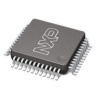
LPC11C24FBD48/301,151 NXP Semiconductors, LPC11C24FBD48/301,151 Datasheet - Page 58

LPC11C24FBD48/301,151
Manufacturer Part Number
LPC11C24FBD48/301,151
Description
Microcontrollers (MCU) CAN Transceiver MCU 32K Flash
Manufacturer
NXP Semiconductors
Datasheet
1.LPC11C22FBD48301151.pdf
(62 pages)
Specifications of LPC11C24FBD48/301,151
Processor Series
LPC11Cx4
Core
ARM Cortex-M0
Data Bus Width
32 bit
Program Memory Type
Flash
Program Memory Size
32 KB
Data Ram Size
8 KB
Interface Type
CAN, I2C, SPI, UART
Maximum Clock Frequency
50 MHz
Number Of Programmable I/os
36
Number Of Timers
4
Operating Supply Voltage
3.3 V
Maximum Operating Temperature
+ 85 C
Mounting Style
SMD/SMT
Development Tools By Supplier
OM13012,598
Minimum Operating Temperature
- 40 C
Lead Free Status / Rohs Status
Details
Other names
935294285151
NXP Semiconductors
15. Revision history
Table 22.
LPC11CX2_CX4
Product data sheet
Document ID
LPC11CX2_CX4 v.3
Modifications:
LPC11CX2_CX4 v.2
Modifications:
LPC11C12_C14 v.1
Revision history
Release date
20110627
20101203
20100921
•
•
•
•
•
•
•
•
•
•
•
•
•
•
•
•
•
•
•
•
I
(minimum) for 2.0 V V
Parameter V
C_CAN power consumption data added to
ADC sampling frequency corrected in
Reflow soldering footprint drawing added
Pull-up level specified in
Parameter T
Condition for parameter T
Table note 4
Table 18
Parts LPC11C22 and LPC11C24 added.
Pin description for parts LPC11C22 and LPC11C24 added (Table 4).
Static characteristics for CAN transceiver added (Table 8).
Description of high-speed, on-chip CAN transceiver added (LPC11C22/C24). See
Section 7.11.2.
Application diagram for connecting the C_CAN to an external transceiver added
(Section 11.6).
Application diagram for high-speed, on-chip CAN transceiver added (Section 11.7).
Typical value for parameter N
Description of RESET and WAKEKUP pins updated in Table 3.
PLL output frequency limited to < 100 MHz in Section 7.16.2 “System PLL”.
Parameter V
2
C-bus pins configured as standard mode pins, parameter I
All information provided in this document is subject to legal disclaimers.
T~cy(clk) condition changed from “when only receiving” to “full-duplex mode”
x
cy(clk)
hys
of
added to
Rev. 3 — 27 June 2011
Data sheet status
Product data sheet
Product data sheet
Product data sheet
Table 5
for I
corrected on
2
C bus pins: typical value corrected V
updated.
Table 5 “Limiting
DD
Table 3
stg
3.6 V.
in
endu
Table 5
Table
and
added in Table 12 “Flash characteristics”.
Table
18.
Table 7 (Table note
Change notice
-
-
-
updated.
values”.
32-bit ARM Cortex-M0 microcontroller
(Section
Table
4.
11.
13).
LPC11Cx2/Cx4
Supersedes
LPC11C12_C14 v.2
LPC11C12_C14 v.1
-
hys
7).
OL
= 0.05V
changed to 3.5 mA
© NXP B.V. 2011. All rights reserved.
DD
in Table 6.
58 of 62


