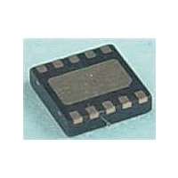
MAX17710G+T Maxim Integrated Products, MAX17710G+T Datasheet - Page 12

MAX17710G+T
Manufacturer Part Number
MAX17710G+T
Description
Battery Management uPower Battery Charger
Manufacturer
Maxim Integrated Products
Datasheet
1.MAX17710GT.pdf
(17 pages)
Specifications of MAX17710G+T
Product
Charge Management
Battery Type
Lithium
Output Voltage
1.8 V, 2.3 V, 3.3 V
Output Current
625 nA
Operating Supply Voltage
5.3 V
Supply Current
50 mA
Maximum Operating Temperature
+ 85 C
Minimum Operating Temperature
- 40 C
Package / Case
DFN-12
Mounting Style
SMD/SMT
Uvlo Start Threshold
3 V
The C1 1nF capacitor acts as a voltage-level feed for-
ward to increase the responsiveness of the divider circuit
as the harvest source capacitor is discharged. The mini-
mum voltage is defined as:
where V
source capacitor during boost.
Because of the divider on the FB pin, the voltage seen by
the LX pin inductor is higher than the typical circuit. The
inductor must be resized so that the LX pin current limits
are not exceeded:
All other components are selected as normal.
When designing an optimal energy harvest system,
there are three types of design approaches: linear har-
vest, boost harvest, and maximum-power-point tracking
(MPPT). In harvesting applications, it is very critical to
not discharge the cell when charging is failing. When
the harvesting power is low enough, eventually the sys-
tem discharges the cell rather than charges. This is the
break-even point of the harvester. For linear harvesting,
this break-even point is lower because the required
quiescent current is less. However, for boost harvesting,
the breakeven threshold is 1FA. While an MPPT system
can utilize the harvesting source more intelligently in
high-power situations, it inevitably results in higher qui-
escent current and a poorer break-even threshold. MPPT
systems must measure the current and voltage, multiply
to determine power, and make decisions to improve the
power. These required measurements automatically
significantly increase the quiescent current budget
by tens of µA.
of operation vs. charge efficiency.
The device regulates voltage from the cell to a load
circuit on the REG pin through an LDO regulator. The
regulator can be configured for 3.3V, 2.3V, or 1.8V opera-
tion. The LDO supports loads up to 75mA (high-current
mode). For lighter load applications, a low-power mode
of operation reduces the quiescent current drain on the
cell. A UVLO circuit prevents the regulator from start-
ing up or disabling the regulator when active if the cell
becomes overdischarged.
LX Inductor = V
V
HARVEST-OFF
V
HARVEST-OFF
Energy-Harvesting Design Approaches
HARVEST-OFF
V
Figure 4
HARVEST-ON
���������������������������������������������������������������� Maxim Integrated Products 12
HARVEST-ON
~= V
~= V
is the lowest voltage of the harvest
Energy-Harvesting Charger and Protector
HARVEST-ON
shows energy-harvesting modes
HARVEST-ON
LDO Output Operation
x (8.5 x 10
x t
BOOST-ON
- (FB
- 0.5V (typ)
-7
ON
)
/LX
- FB
IMAX
OFF
=
)
Figure 3. FB Divider Circuit to Improve Boost Efficiency for
Charge Sources Between 1.0V and 2.0V
Figure 4. Energy-Harvesting Modes of Operation vs. Charge
Efficiency
1.0V TO 2.0V
CHARGE
SOURCE
THRESHOLDS
BREAK-EVEN
47µF
HARVEST
POWER FROM HARVEST SOURCE
LINEAR
1nF
C1
0.1µF
R2
R1
500kI
ZLLS410TA
L1
MAX17710
LX
FB
CHG
MAX17710
BOOST HARVEST
(MAX POWER
TRACKING)
MPPT


