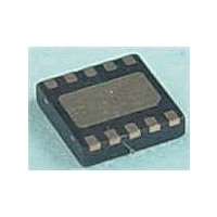
MAX17710G+T Maxim Integrated Products, MAX17710G+T Datasheet - Page 7

MAX17710G+T
Manufacturer Part Number
MAX17710G+T
Description
Battery Management uPower Battery Charger
Manufacturer
Maxim Integrated Products
Datasheet
1.MAX17710GT.pdf
(17 pages)
Specifications of MAX17710G+T
Product
Charge Management
Battery Type
Lithium
Output Voltage
1.8 V, 2.3 V, 3.3 V
Output Current
625 nA
Operating Supply Voltage
5.3 V
Supply Current
50 mA
Maximum Operating Temperature
+ 85 C
Minimum Operating Temperature
- 40 C
Package / Case
DFN-12
Mounting Style
SMD/SMT
Uvlo Start Threshold
3 V
PIN
10
11
12
—
1
2
3
4
5
6
7
8
9
NAME
PGND
PCKP
����������������������������������������������������������������� Maxim Integrated Products 7
BATT
SEL2
SEL1
CHG
GND
REG
LCE
FB
LX
AE
EP
Energy-Harvesting Charger and Protector
Cell Input. Connect to the positive terminal of the cell without a bypass capacitor.
Charge Input. The IC charges the cell from the power source applied to this pin. Connect to the
output of the boost circuit or directly to a 4.21V or higher charge source.
Boost Enable. The boost circuit is enabled by driving this pin above the FB
the boost circuit is disabled by driving this pin below FB
Device Ground. Connect to system ground.
Boost Input. Controls current drive through inductor of external boost circuit.
Power Ground. Connect to system ground.
Active Enable. Pulse high to enable high-power regulator output. Pulse low to disable regulator
output.
Boost R
applications.
Regulator Voltage Select. Ground this pin to select a regulator output voltage of 2.3V, leave
disconnected for a regulator output voltage of 3.3V, or connect to the BATT pin for a regulator
output voltage 1.8V.
Regulator Output. Connect to load circuit.
Low-Current Enable. Pulse high to enable the low-current regulator output after the high-current
regulator output is already active. Pulse low to disable.
Protected Output of Pack. Connect an external 10FF or greater capacitor to PCKP to support energy
buffering to the load, especially in low-temperature applications. PCKP is used for pulsed current
storage.
Exposed Pad. Connect to GND.
DS-ON
TOP VIEW
Select. Connect to system ground to select a boost R
PGND
BATT
CHG
GND
FB
LX
1
2
3
4
5
6
+
MAX17710
UTDFN
FUNCTION
EP
12
11
10
9
8
7
OFF
PCKP
LCE
REG
SEL1
SEL2
AE
.
DS-ON
Pin Configuration
MAX17710
Pin Description
ON
of 0.5I for typical
threshold. Afterwards,


