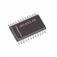
MAX260BCWG+ Maxim Integrated Products, MAX260BCWG+ Datasheet - Page 18

MAX260BCWG+
Manufacturer Part Number
MAX260BCWG+
Description
IC FILTER ACT MPU PROG 24-SOIC
Manufacturer
Maxim Integrated Products
Datasheet
1.MAX262BCNG.pdf
(26 pages)
Specifications of MAX260BCWG+
Filter Type
Universal Switched Capacitor
Frequency - Cutoff Or Center
7.5kHz
Number Of Filters
2
Max-order
2nd
Voltage - Supply
4.74 V ~ 12.6 V, ±2.37 V ~ 6.3 V
Mounting Type
Surface Mount
Package / Case
24-SOIC (7.5mm Width)
Lead Free Status / RoHS Status
Lead free / RoHS Compliant
BANDPASS (Figure 12)
For all pole bandpass and lowpass filters (Butterworth,
Bessel, Chebyshev) use mode 1 if possible. If appropri-
ate f
mode 2 provides a selection that is closer to the
required values. Mode 1, however, has the highest
bandwidth (see Table 1). For pole-zero filters, such as
elliptics, see mode 3A.
H
f
Q = The quality factor of the complex pole pair.
LOWPASS See bandpass text. (Figure 13)
H
f
HIGHPASS (Figure 14)
Mode 3 is the only mode with a highpass output. It
works for all pole filter types such as Butterworth,
Bessel and Chebyshev. Use mode 3A for filters
employing both poles and zeros, such as elliptics.
Microprocessor Programmable
Universal Active Filters
Figure 11. Filter Mode 4: Second-Order Bandpass, Lowpass,
and Allpass
18
G s
0
G s
0
OBP
OLP
( )
= ω
( )
= ω
IN
CLK
pole pair. Input-output phase shift is -180° at f
Also the ratio of f
second-order bandpass response.
______________________________________________________________________________________
0
=
= Lowpass output gain at DC
= Bandpass output gain at ω = ω
0
=
Description of Filter Functions
/ 2π
/ 2π = The center frequency of the complex
SCN
H
/f
H
0
OBP
OLP
or Q values are not available in mode 1,
s
s
SCN = SWITCHED-CAPACITOR NETWORK
2
2
+
SCN
SCN
+
-
+
s
s
0
s
(
(
ω
ω
(
to -3dB bandwidth of the
ω
o
o
ω
MODE 4
o
o
/
/
2
/
+
Q
Q
Q
)
)
Σ
)
+
+
-
-
ω
ω
o
o
∫
2
AP
2
o
∫
0
.
BP
LP
H
f
NOTCH (Figure 15)
Mode 3A is recommended for multi-pole notch filters. In
second-order filters, mode 1 can also be used. The
advantages of mode 1 are higher bandwidth, com-
pared to mode 3 (higher f
no need for external components as required in mode
3A.
H
H
f
ALLPASS
Mode 4 is the only configuration in which an allpass
function can be realized.
Figure 12. Second-Order Bandpass Characteristics
0
n
G s
G s
OHP
ON2
ON1
= ω
( )
= ω
( )
0
n
=
= Notch output gain as f approaches f
= Notch output gain as f approaches DC
= Highpass output gain as f approaches f
=
/ 2π
/ 2π
0.707 H
H
H
ON
OHP
H
OBP
OBP
2
s
Q
f
f
s
L
H
2
2
=
=
=
+
+
f
f
f
H
O
O
s
s
s
(
(
f
ω
2
ω
O
−
2
2
−
o
o
Q
1
+
f
Q
1
BANDPASS OUTPUT
L
s
N
/
/
,
2
f(LOG SCALE)
+
ω
+
Q
Q
f
O
f
can be implemented), and
L
n
)
)
2
=
+
+
2
2
f
1
Q
1
O
Q
f f
L H
ω
ω
+
+
2
o
2
o
f
H
2
2
1
1
CLK
CLK
/4
/4


