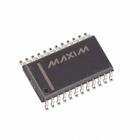
MAX260BCWG+ Maxim Integrated Products, MAX260BCWG+ Datasheet - Page 8

MAX260BCWG+
Manufacturer Part Number
MAX260BCWG+
Description
IC FILTER ACT MPU PROG 24-SOIC
Manufacturer
Maxim Integrated Products
Datasheet
1.MAX262BCNG.pdf
(26 pages)
Specifications of MAX260BCWG+
Filter Type
Universal Switched Capacitor
Frequency - Cutoff Or Center
7.5kHz
Number Of Filters
2
Max-order
2nd
Voltage - Supply
4.74 V ~ 12.6 V, ±2.37 V ~ 6.3 V
Mounting Type
Surface Mount
Package / Case
24-SOIC (7.5mm Width)
Lead Free Status / RoHS Status
Lead free / RoHS Compliant
Start with the program “PZ” to determine what type of
filter is needed. This helps determine the type
(Butterworth, Chebyshev, etc.) and the number of poles
for the optimum choice. The program also plots the fre-
Microprocessor Programmable
Universal Active Filters
Figure 2. Basic Program and Hardware Connections to Parallel Printer Port for “Quick Look” Using a PC
8
_______________________________________________________________________________________
OUT
IN
100
110
120
130
140
150
160
170
180
190
200
210
220
230
240
250
260
270
280
290
300
310
(20)14
*PIN NUMBERS IN ( ) ARE FOR MAX261/MAX262
Step 1—Filter Design
24
23
22
21
5
3
1
AB$ = "FILTER A" : GOSUB 150 : REM GET DATA FOR SECTION A
ADD = 0 : GOSUB 220 : REM WRITE DATA TO THE PRINTER PORT
AB$ = "FILTER B" : GOSUB 150 : REM GET DATA FOR B
ADD = 32 : GOSUB 220 : REM WRITE DATA TO PRINTER PORT
GOTO 100
PRINT "MODE (1 to 4, see Table 5) "; AB$; : INPUT M
IF M<1 OR M>4 THEN GOTO 150
PRINT "CLOCK RATIO (0 to 63, N of Table 2) "; AB$; : INPUT F
IF F<0 OR F>63 THEN GOTO 170
PRINT "Q (0 to 127, N of Table 3) "; AB$; : INPUT Q
IF Q<0 OR Q>127 THEN GOTO 190 ELSE : PRINT
RETURN
LPRINT CHR$(ADD+M-1); : ADD = ADD+4
FOR I = 1 TO 3
X = (ADD + (F - 4*INT(F/4))) : LPRINT CHR$(X);
F=INT(F/4) : ADD = ADD + 4
NEXT I
FOR I = 1 TO 4
X=(ADD + (Q - 4*INT(Q/4))) : LPRINT CHR$(X);
Q=I (Q/4) :: ADD = ADD + 4
NEXT I
RETURN
IN
LP
HP
BP
IN
LP
HP
BP
+5V
V
A
B
A
A
B
B
A
B
+
9
0.1µF
MAX261*
MAX262*
MAX260
GND
18(17)
0.1µF
CLK
CLK
-5V
WR
V
D0
D1
A0
A1
A2
A3
-
A
B
17(16)
16(15)
20(19)
6
15(14)
13
10
7
11
12
(SEE FIGURE 4)
CLK IN
quency response and calculates the pole/zero (f
Q values for each second-order section. Each
MAX260/MAX261/MAX262 contains two second-order
sections, and devices can be cascaded for higher
order filters.
TTL
11
12
1
2
3
4
5
6
7
25
24
23
22
21
20
19
18
DB-25 MALE PLUG
(BACK VIEW)
0
) and


