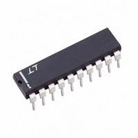
LTC1061ACN Linear Technology, LTC1061ACN Datasheet - Page 13

LTC1061ACN
Manufacturer Part Number
LTC1061ACN
Description
IC FILTER BUILDNG BLK TRPL 20DIP
Manufacturer
Linear Technology
Datasheet
1.LTC1061CNPBF.pdf
(16 pages)
Specifications of LTC1061ACN
Filter Type
Universal Switched Capacitor
Frequency - Cutoff Or Center
35kHz
Number Of Filters
3
Max-order
6th
Voltage - Supply
4.74 V ~ 16 V, ±2.37 V ~ 8 V
Mounting Type
Through Hole
Package / Case
20-DIP (0.300", 7.62mm)
Lead Free Status / RoHS Status
Contains lead / RoHS non-compliant
Available stocks
Company
Part Number
Manufacturer
Quantity
Price
Company:
Part Number:
LTC1061ACN#PBF
Manufacturer:
LT
Quantity:
1 001
W
Figure 21 shows the side A of the LTC1061 connected in
Mode 2 while sides B and C are in Mode 3a. This topology
can be used to synthesize elliptic bandpass, highpass and
notch filters. The elliptic highpass of Figure 17 is synthe-
sized again, Figure 22, but the clock is now locked onto the
Figure 22. 6th Order Elliptic Highpass Filter Operating with a
Clock-to-Cutoff Frequency Ratio of 75:1 and Using the Topology
of Figure 21
CLOCK INPUT
Figure 21. LTC1061 with Side A is Connected in Mode 2 While
Side B, C are in Mode 3a. Topology is Useful for Elliptic
Highpass, Notch and Bandpass Filters.
–10
–20
–30
–40
–50
–60
–70
–80
–90
T
ODES OF OPERATIO
2
0
L, CMOS
0
V
V
1
IN
+
R33
R23
2
R43
3
4
f
IN
10
(kHz)
5
1
2
3
4
5
6
7
8
9
6
LTC1061
7
8
R
R
h
l
2
2
9
20
19
18
17
16
15
14
13
12
11
10
NOTE: FOR CLOCK FREQUEN-
CIES ABOVE 300kHz, ADD
A CAPACITOR C ACROSS
R21 AND R22 SUCH AS
(1/2πR21C) = f
R11 = 54.9k
R31 = 34.8k
R
R22 = 68.1k
R42 = 10k
R
R33 = 75k
h
l
U
2 = 16.2k
1 = 28.7k
V
–
RESISTOR VALUES
STANDARD 1%
R42
R32
R22
R
R41
R31
R21
R11
R
l
h
1
1
CLK
V
R21 = 24.3k
R41 = 10k
R
R32 = 18.2k
R
R23 = 10k
R43 = 14k
OUT
l
h
1 = 280k
2 = 10.2k
1061 F21
1061 F22
higher frequency notch provided by the side A of the
LTC1061. As shown in Figure 22, the highpass corner
frequency is 3.93kHz and the higher notch frequency is
3kHz while the filter operates with a 300kHz clock. The
center frequencies, Qs, and notches of Figure 22, when
normalized to the highpass cutoff frequency, are (f
1.17, Q1 = 2.24, f
f
topology of Figure 16, this approach uses lower and more
restricted clock frequencies. The obtained notch in Mode
2 is shallower although the topology is more efficient.
Output Noise
The wideband RMS noise of the LTC1061 outputs is nearly
independent from the clock frequency. The LTC1061
noise when operating with ±2.5V supply is lower, as Table
3 indicates. The noise at the bandpass and lowpass
outputs increases rough as the √Q. Also the noise in-
creases when the clock-to-center frequency ratio is al-
tered with external resistors to exceed the internally set
100:1 or 50:1 ratios. Under this condition, the noise
increases square root-wise.
Output Offsets
The equivalent input offsets of the LTC1061 are shown in
Figure 23. The DC offset at the filter bandpass output is
always equal to V
outputs (Notch and LP) depend on the mode of operation
and external resistor ratios. Table 4 illustrates this.
It is important to know the value of the DC output offsets,
especially when the filter handles input signals with large
dynamic range. As a rule of thumb, the output DC offsets
increase when:
1. The Qs decrease
2. The ratio (f
O3
= 0.987, f
done by decreasing either the (R2/R4) or the R6/(R5
+ R6) resistor ratios.
n3
= 0.753, Q3 = 10). When compared with the
CLK
n1
OS3
/f
= 0.242, f
. The DC offsets at the remaining two
O
) increases beyond 100:1. This is
O2
= 1.96, Q2 = 0.7, f
LTC1061
n2
13
= 0.6,
O1
1061fe
=


