293D337X9010E2T Vishay, 293D337X9010E2T Datasheet - Page 10
293D337X9010E2T
Manufacturer Part Number
293D337X9010E2T
Description
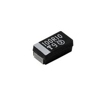
Tantalum Capacitors - Solid SMD 330uF 10volts 10% E case
Manufacturer
Vishay
Series
293Dr
Datasheet
1.293D337X06R3E2T.pdf
(13 pages)
Specifications of 293D337X9010E2T
Capacitance
330 uF
Voltage Rating
10 Volts
Esr
0.5 Ohms
Tolerance
10 %
Operating Temperature Range
- 55 C to + 85 C
Package / Case
7343-43 metric
Dimensions
4.3 mm W x 7.3 mm L
Height
4 mm
Mfr Case Code
E Case
Product
Tantalum Solid Low ESR Commercial Grade
Dissipation Factor Df
10
Lead Spacing
1.3 mm
Leakage Current
33 uAmps
Ripple Current
0.57 Amp
Termination Style
SMD/SMT
Lead Free Status / Rohs Status
No RoHS Version Available


PERFORMANCE CHARACTERISTICS
12.4
12.5
12.6
13.
13.1
13.2
14.
14.1
14.2
14.3
14.4
15.
15.1
15.1.1 Following the resistance to soldering heat test,
15.2
16.
17.
Document Number: 40002
Revision: 25-Apr-05
Electrical tests shall show no evidence of intermittent
contacts, open circuits or short circuits during these
tests.
There shall be no mechanical damage to these
capacitors as a result of these tests.
Following the shock test, capacitors shall meet the
original limits for capacitance, dissipation factor and
leakage current.
Moisture Resistance:
Capacitors shall be subjected to temperature cycling
at 90 % to 95 % relative humidity, from + 25 °C to
+ 65 °C to + 25 °C (+ 10 °C, - 2 °C) over a period of 8
hours per cycle for 1000 hours.
Following the moisture resistance test, the leakage
current and dissipation factor shall meet the initial
requirements, and the change in capacitance shall
not exceed ±10%.
Thermal Shock:
Capacitors shall be conditioned prior to temperature
cycling for 15 minutes at + 25 °C, at less than 50 %
relative humidity and a barometric pressure at 28 to
31"
Capacitors shall be subjected to thermal shock in a
cycle of exposure to ambient air at :
- 55 °C (+ 0 °C,- 5 °C) for 30 minutes, then
+ 25 °C (+ 10 °C, - 5 °C) for 5 minutes, then
+ 125 °C (+ 3 °C, - 0 °C) for 30 minutes, then
+ 25 °C (+ 10 °C, - 5 °C) for 5 minutes for 5 cycles.
Capacitors shall show no evidence of harmful or
extensive corrosion, obliteration of marking or other
visible damage.
Following the thermal shock test, capacitors shall
meet the original requirements for leakage current
and dissipation factor. Capacitance change shall not
exceed ± 5 % of the original measured value.
Soldering Compatibility:
Resistance to Solder Heat: Capacitors will
withstand exposure to + 260 °C + 5 °C for 10
seconds.
capacitance, dissipation factor and DC leakage
current shall meet the initial requirement.
Solderability: Capacitors will meet the solderability
requirements of ANSI/J-STD-002, Test B, Category
3.
Terminal Strength: Per UEC-384-3, minimum of 5N
shear force.
Environmental: Mercury, CFC and ODS materials
are not used in the manufacture of these capacitors.
TANTAMOUNT®, Commercial, Surface Mount
For technical questions, contact: tantalum@vishay.com
Solid Tantalum Chip Capacitors
(Continued)
18.
19.
20.
GUIDE TO APPLICATION
1.
Standard Conditions, for example; output filters
Severe Conditions, for example; input filters
2.
Capacitor Voltage Rating (V)
Capacitor Voltage Rating (V)
Flammability: Encapsulant materials meet UL94 V0
with an oxygen index of 32 %.
Capacitor Failure Mode: The predominant failure
mode for solid tantalum capacitors is increased
leakage current resulting in a shorted circuit.
Capacitor failure may result from excess forward or
reverse DC voltage, surge current, ripple current,
thermal shock or excessive temperature.
The increase in leakage is caused by a breakdown of
the Ta
leakage failure of solid tantalum chip capacitors, refer
to Vishay Sprague Technical Paper, “Leakage Failure
Mode in Solid Tantalum Chip Capacitors.”
Surge Current: All D and E case code 293D
capacitors are 100 % surge current tested at + 25 °C
and rated voltage. The total series circuit resistance is
0.5 ohms. Each charge cycle of 0.10 seconds is
followed by a discharge cycle of 0.10 seconds. Three
surge cycles are applied. Each capacitor is tested
individually to maximize the peak charging current.
Recommended rated working voltage guidelines:
(-55 °C to + 85 °C)
A-C Ripple Current: The maximum allowable ripple
current shall be determined from the formula:
where,
P =
R
ESR
=
I
4.0
6.3
4.0
6.3
10
16
20
25
35
50
10
16
20
25
35
50
2
rms
O
5
given in the table in Paragraph Number 5
(Power Dissipation)
The capacitor Equivalent Series
Resistance at the specified frequency.
Power Dissipation in Watts at + 25 °C as
dielectric. For additional information on
=
--------------- -
R
ESR
P
Operating Voltage (V)
Operating Voltage (V)
Vishay Sprague
2.5
3.6
6.0
2.5
3.3
5.0
8.0
10
12
15
24
28
10
12
15
24
www.vishay.com
293D
10
Related parts for 293D337X9010E2T
Image
Part Number
Description
Manufacturer
Datasheet
Request
R

Part Number:
Description:
357-036-542-201 CARDEDGE 36POS DL .156 BLK LOPRO
Manufacturer:
Vishay
Datasheet:
Part Number:
Description:
357-036-542-201 CARDEDGE 36POS DL .156 BLK LOPRO
Manufacturer:
Vishay
Datasheet:
Part Number:
Description:
357-036-542-201 CARDEDGE 36POS DL .156 BLK LOPRO
Manufacturer:
Vishay
Datasheet:
Part Number:
Description:
357-036-542-201 CARDEDGE 36POS DL .156 BLK LOPRO
Manufacturer:
Vishay
Datasheet:
Part Number:
Description:
357-036-542-201 CARDEDGE 36POS DL .156 BLK LOPRO
Manufacturer:
Vishay
Datasheet:
Part Number:
Description:
357-036-542-201 CARDEDGE 36POS DL .156 BLK LOPRO
Manufacturer:
Vishay
Datasheet:
Part Number:
Description:
357-036-542-201 CARDEDGE 36POS DL .156 BLK LOPRO
Manufacturer:
Vishay
Datasheet:
Part Number:
Description:
357-036-542-201 CARDEDGE 36POS DL .156 BLK LOPRO
Manufacturer:
Vishay
Datasheet:
Part Number:
Description:
357-036-542-201 CARDEDGE 36POS DL .156 BLK LOPRO
Manufacturer:
Vishay
Datasheet:
Part Number:
Description:
357-036-542-201 CARDEDGE 36POS DL .156 BLK LOPRO
Manufacturer:
Vishay
Datasheet:
Part Number:
Description:
357-036-542-201 CARDEDGE 36POS DL .156 BLK LOPRO
Manufacturer:
Vishay
Datasheet:
Part Number:
Description:
357-036-542-201 CARDEDGE 36POS DL .156 BLK LOPRO
Manufacturer:
Vishay
Datasheet:
Part Number:
Description:
357-036-542-201 CARDEDGE 36POS DL .156 BLK LOPRO
Manufacturer:
Vishay
Datasheet:
Part Number:
Description:
357-036-542-201 CARDEDGE 36POS DL .156 BLK LOPRO
Manufacturer:
Vishay
Datasheet:
Part Number:
Description:
357-036-542-201 CARDEDGE 36POS DL .156 BLK LOPRO
Manufacturer:
Vishay
Datasheet: