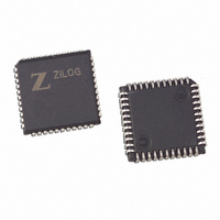
Z0220112VEGR4078 Zilog, Z0220112VEGR4078 Datasheet - Page 31

Z0220112VEGR4078
Manufacturer Part Number
Z0220112VEGR4078
Description
IC MODEM 2400BPS DSP AFE 44-PLCC
Manufacturer
Zilog
Specifications of Z0220112VEGR4078
Data Format
V.21, V.22, V.23, Bell 103, Bell 212A
Baud Rates
2.4k
Interface
Parallel
Voltage - Supply
4.5 V ~ 5.5 V
Mounting Type
Surface Mount
Package / Case
44-LCC (J-Lead)
Lead Free Status / RoHS Status
Lead free / RoHS Compliant
Available stocks
Company
Part Number
Manufacturer
Quantity
Price
Table 17. REG5: Data Pump Status Register
PS000904-0107
SYMBOL
RES
CDET
RTRND
Reserved
DPBUSY
RAMl
RXl
TXl
Note: The RXI bit is set to 1 after the reset sequences. All other bits in this register (Reg. 5) default to 0 at power up
Bit
or after reset sequences are completed.
TXI
7
POSITION
REG 5, bit 0
REG 5, bit 1
REG 5, bit 2
REG 5, bit 3
REG 5, bit 4
REG 5, bit 5
REG 5, bit 6
REG 5, bit 7
RXI
6
NAME AND DESCRIPTION
Data Pump in RESET Mode. This bit is set whenever the data pump is in
Receive Interrupt Status. This bit is set when the data pump is in parallel
RESET mode because of a hardware reset or power-on. The data pump
sets RES to 0 when it completes the reset cycle.
Carrier Detect. The data pump sets CDET to 1 when it enters any data mode
and is ready to transmit data. The data pump sets CDET to 0 during retrains
(see Reg5, bit 2, RTRND), and when no signal is detected from the remote
modem. See locations RLSDOnThresh and RLSDOffThresh for more
information. CDET is inverted and reflected on the data pump’s RLSD pin. If
CDET is 1, RLSD is Low (asserted). At any reset, or when the host sets
Config register, bits 0–6 (MODE)
CDET to 0.
Retrain Detect, 2400 bps (V.22bis data mode only). The Retrain sequence is
detected when this bit is set. The data pump has detected a retrain request
sequence from the remote modem.
Reserved bit location.
Data Pump Busy. This bit is set whenever the data pump starts transmitting
data and RTSP is 1. When the link is to be terminated, setting RTSP to 0
causes this bit to be reset after the data pump has finished transmitting the
most recent data in its internal buffers. When this bit has been reset, it is
safe to set Config. register, bits 0–6 (MODE) to standby mode (0) and hang
up the telephone, terminating the connection. This bit also indicates when
digits are being dialed during timed dialing operation. At any reset, or when
the host sets Config register, bits 0–6
pump sets DPBUSY to 0. This bit is not valid during HDLC operation.
Data Pump RAM Interrupt Status. This bit is set when the data pump has
processed a RAM read/write request.
data transfer mode (TPDM is 1) and the data pump has written a new octet
to the DATAP register. A read from the DATAP register clears this bit.
Transmit Interrupt Status. This bit is set when the data pump is in parallel
data transfer mode (TPDM is 1) and the data pump has read the DATAP
register. A write to the DATAP register clears this bit.
RAMI
5
DPBUSY
4
Reserved
3
V.22BIS Data Pump with Integrated AFE
RTRND
2
to 0 (STANDBY), the data pump sets
(MODE)
CDET
1
to 0 (STANDBY) the data
RES
0
27


