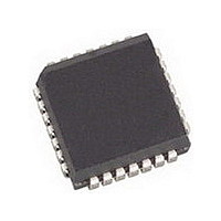
AMIS49587C5871RG ON Semiconductor, AMIS49587C5871RG Datasheet - Page 21

AMIS49587C5871RG
Manufacturer Part Number
AMIS49587C5871RG
Description
IC MODEM PLC 50/60MHZ 28PLCC
Manufacturer
ON Semiconductor
Specifications of AMIS49587C5871RG
Baud Rates
Selectable
Interface
SCI
Voltage - Supply
3 V ~ 3.6 V
Mounting Type
Surface Mount
Package / Case
28-PLCC
Number Of Transmitters
1
Power Supply Requirement
Single
Package Type
PLCC
Operating Temperature Classification
Commercial
Mounting
Surface Mount
Pin Count
28
Operating Temperature (max)
70C
Dual Supply Voltage (typ)
Not RequiredV
Dual Supply Voltage (max)
Not RequiredV
Dual Supply Voltage (min)
Not RequiredV
Lead Free Status / RoHS Status
Lead free / RoHS Compliant
Data Format
-
Lead Free Status / Rohs Status
Compliant
Available stocks
Company
Part Number
Manufacturer
Quantity
Price
Company:
Part Number:
AMIS49587C5871RG
Manufacturer:
ON
Quantity:
3 400
Company:
Part Number:
AMIS49587C5871RG
Manufacturer:
ON Semiconductor
Quantity:
10 000
6.1.4 Clock Generator and Timer
of timing signals used for the synchronization and interrupt
generation. The timing generation has a fixed repetition rate
which corresponds to the length of a physical subframe. (see
paragraph Send and Receive network data).
CHIP_CLK is the output of the PLL and 8 times the bit rate on the physical interface. See also paragraph 50/60 Hz PLL
BIT_CLK is active at counter values 0,8,16, .. 2872 and inactive at all other counter values. This signal is used to indicate
the transmission of a new bit.
BYTE_CLK is active at counter values 0,64,128, .. 2816 and inactive at all other counter values. This signal is used to indicate
the transmission of a new byte.
FRAME_CLK is active at counter values 0 and inactive at all other counter values. This signal is used to indicate the
transmission or reception of a new frame.
PRE_BYTE_CLK is a signal which is 8 CHIP_CLK sooner than BYTE_CLK. This signal is used as an interrupt for the
internal microcontroller and indicates that a new byte for transmission must be generated.
PRE_FRAME_CLK is a signal which is 8 CHIP_CLK sooner than FRAME_CLK. This signal is used as an interrupt for
the internal microcontroller and indicates that a new frame will start at the next FRAME_CLK.
PRE_SLOT is logic 1 between the rising edge of PRE_FRAME_CLK and the rising edge of FRAME_CLK. This signal can
be provided at the digital output pin TX_DATA_PRE_SLOT when R_CONF[7] = 0 (See paragraph WriteConfigRequest, field
TX_DATA_PRE- -SLOT_SEL) and can be used by the external host controller to synchronize its software with the
FRAME_CLK of AMIS- -49587.
PRE_FRAME_CLK
The CHIP_CLK and f
PRE_BYTE_CLK
FRAME_CLK
PRE_SLOT
BYTE_CLK
R_CHIP_CNT
CHIP_CLK
BIT_CLK
2871 2872
CLK
are used to generate a number
Start of the physical subframe
2879
0
Figure 16. Timing Signals
1
http://onsemi.com
2
21
3
mode. When AMIS- -49587 switches from receive to
transmit and back from transmit to receive, the
R_CHIP_CNT counter value is maintained. As a result all
timing signals for receive and transmit have the same
relative timing. The following timing signals are defined as:
The timing generator is the same for transmit and receive
4
5
6
7
8
9
63
64
65


