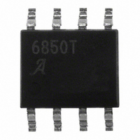
A6850KLTR-T Allegro Microsystems Inc, A6850KLTR-T Datasheet - Page 3

A6850KLTR-T
Manufacturer Part Number
A6850KLTR-T
Description
IC SWITCH INTERFACE 2CHAN 8-SOIC
Manufacturer
Allegro Microsystems Inc
Type
Hall Effect Switchr
Datasheet
1.A6850KLTR-T.pdf
(12 pages)
Specifications of A6850KLTR-T
Input Type
Voltage
Output Type
Voltage
Interface
2-Wire Serial
Current - Supply
5mA
Mounting Type
Surface Mount
Package / Case
8-SOIC (3.9mm Width)
Interface Applications
Microprocessors, 2 Wire Hall Effect Sensor IC
Supply Voltage Range
4.75V To 26.5V
Power Dissipation Pd
52mW
Operating Temperature Range
-40°C To +125°C
Lead Free Status / RoHS Status
Lead free / RoHS Compliant
Other names
620-1185-2
Available stocks
Company
Part Number
Manufacturer
Quantity
Price
Company:
Part Number:
A6850KLTR-T
Manufacturer:
ADI
Quantity:
1 131
A6850
ELECTRICAL CHARACTERISTICS at T
Supply Input Voltage Range
Supply Input Quiescent Current
Power-Up Time
OUTPUTx Source Resistance
OUTPUTx Leakage Current
SENSEx Output Current Offset
SENSEx Voltage
ENABLEx Input Voltage Range
ENABLEx Input Hysteresis
ENABLEx Current
OUTPUT Current Limit
OUTPUT Reverse Bias Current
Overvoltage Protection Threshold
Overvoltage Protection Hysteresis
Thermal Shutdown Threshold
Thermal Shutdown Hysteresis
1
2
3
4
internal clamp, but not all parameters perform as specified.
Output Rise Time
Output Fall Time
Enable Delay Time
Disable Delay Time
Delay from end of Sleep mode to outputs enabled.
For input and output current specifications, negative current is defined as coming out of (sourced from) the specified device pin.
User to ensure that V
R
SENSEx
Characteristics
= 1.5 kΩ.
1
4
2
2
2
2
SENSEx
remains within the specified range. If V
3
I
V
OUTPUT(rvrs)
I
V
I
V
I
SENSE(ofs)
Symbol
V
OUTPUTQ
I
ENABLEhys
OUTPUTM
V
t
I
T
t
R
SENSEQ
ENABLEH
ENdlyLH
ENdlyHL
ENABLEL
ENABLE
SENSEx
V
OVPhys
T
TSDhys
J
DS(on)
I
t
V
t
t
INQ
ON
rLH
fHL
OVP
TSD
= -40 to +150°C (unless noted otherwise)
IN
Operating mode, I
Sleep mode:
ENABLE1 and ENABLE2 low
V
I
V
I
I
V
V
V
At least one output enabled
ENABLEx = 2.0 V
ENABLEx = 0.4 V
Reverse bias blocking: V
V
Rising V
Temperature Increasing
I
10% to 90%V
I
90% to 10%V
I
50% ENABLEx to 50%V
I
50% ENABLEx to 50%V
OUTPUTx
SENSEx
OUTPUT
OUTPUTx
OUTPUTx
OUTPUTx
OUTPUTx
OUTPUT1
OUTPUTx
SENSEx
IN
IN
OUTPUT
> 7 V
< 7 V
= (I
= –2 mA to –20 mA
IN
= 0 V; disabled
= –20 mA
= 26.5 V
Dual Channel Switch Interface IC
= 0 to –10 mA,
= 0 to –10 mA,
= –5 mA,
= –5 mA,
SENSEx
= 0 V; disabled
= V
Test Conditions
OUTPUTx
OUTPUT2
SENSEx
SENSEx
exceeds the maximum value, the device is self-protected by an
OUTPUTx
/ 10) + I
= 0 V
SENSEx
SENSEx
IN
= 0 mA
= 4.75 V,
SENSE(ofs)
,
–25.0
115 Northeast Cutoff
1.508.853.5000; www.allegromicro.com
–100
Allegro MicroSystems, Inc.
Worcester, Massachusetts 01615-0036 U.S.A.
Min.
4.75
27.0
125
2.0
–
–
–
–
–
–
–
–
–
–
0
0
–
–
–
–
–
–
–
–35.0
Typ.
0.18
150
500
175
1.4
4.0
8.0
2.0
40
15
–
–
–
–
–
–
–
–
–
–
–
–
–
–
V
–45.0
Max.
26.5
33.0
500
–20
100
IN
375
100
750
5.0
1.5
3.5
7.5
0.4
15
20
35
10
20
6
–
–
–
–
– 1
Units
mA
mV
mA
μA
μA
μA
μA
μA
μA
μA
μs
μs
μs
ns
μs
°C
°C
Ω
V
V
V
V
V
V
V
3


