AD9895KBCZRL Analog Devices Inc, AD9895KBCZRL Datasheet - Page 39
AD9895KBCZRL
Manufacturer Part Number
AD9895KBCZRL
Description
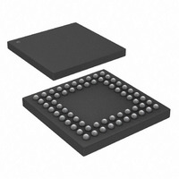
IC CCD SIGNAL PROC/GEN 64-CSPBGA
Manufacturer
Analog Devices Inc
Type
CCD Signal Processor, 12-Bitr
Datasheet
1.AD9895KBCZRL.pdf
(58 pages)
Specifications of AD9895KBCZRL
Input Type
Logic
Output Type
Logic
Interface
3-Wire Serial
Mounting Type
Surface Mount
Package / Case
64-CSPBGA
Analog Front End Type
CCD
Analog Front End Category
Video
Interface Type
Serial (3-Wire)
Sample Rate
30MSPS
Operating Supply Voltage (min)
2.7/3V
Resolution
12b
Number Of Adc's
1
Power Supply Type
Analog/Digital
Operating Temp Range
-20C to 85C
Operating Temperature Classification
Commercial
Mounting
Surface Mount
Pin Count
64
Number Of Channels
1
Lead Free Status / RoHS Status
Lead free / RoHS Compliant
Current - Supply
-
Lead Free Status / RoHS Status
Compliant, Lead free / RoHS Compliant
Available stocks
Company
Part Number
Manufacturer
Quantity
Price
Company:

Part Number:
AD9895KBCZRL
Manufacturer:
Analog Devices Inc
Quantity:
10 000


VERTICAL TIMING EXAMPLE
Figure 49 shows an example CCD timing chart for an interlaced
readout. Each field can be broken down into four separate region
areas. The vertical region change positions (RCPs) will set the
line boundaries for each region area, and the region pointers will
assign a unique region to each region area.
Region Area 0 is a high speed vertical shift region. Sweep Mode
can be used to generate this timing operation, with the desired
number of high speed vertical pulses needed to “clean” the
charge from the CCD’s vertical registers.
Region Area 1 consists of only two lines and uses standard
single line vertical shift timing. The timing of this region area
will be the same as the timing in Region Area 3.
REV. A
V1/VSG1
V3/VSG2
SUBCK
MSHUT
VSUB
CCD
OUT
VD
HD
V2
V4
EXPOSURE PERIOD (
OPEN
CLOSE
t
EXP
)
REGION
AREA 0
Figure 49. Vertical Timing Example—Separate Regions
REGION
AREA 1
REGION
AREA 2
INTERLACED READOUT PERIOD
REGION
AREA 3
–39–
Region Area 2 is the sensor gate line, where the VSG pulses trans-
fer the image into the vertical CCD registers. This region will
require the use of the second vertical sequence for SG lines.
Region Area 3 also uses the standard single line vertical shift
timing, the same timing as Region Area 1.
In summary, three unique regions are required to support the four
region areas, since Region Areas 1 and 3 use the same timing.
Some of the timing parameters will need to be adjusted to read out
the second field, such as the sensor gate pulse and line location.
AD9891/AD9895
OPEN
Related parts for AD9895KBCZRL
Image
Part Number
Description
Manufacturer
Datasheet
Request
R

Part Number:
Description:
±1.7g Dual-Axis IMEMS Accelerometer Evaluation Board
Manufacturer:
Analog Devices Inc
Datasheet:

Part Number:
Description:
Inertial Sensor Evaluation System
Manufacturer:
Analog Devices Inc
Datasheet:
Part Number:
Description:
Manufacturer:
Analog Devices Inc
Datasheet:
Part Number:
Description:
Manufacturer:
Analog Devices Inc
Datasheet:
Part Number:
Description:
Manufacturer:
Analog Devices Inc
Datasheet:
Part Number:
Description:
Manufacturer:
Analog Devices Inc
Datasheet:
Part Number:
Description:
Manufacturer:
Analog Devices Inc
Datasheet:
Part Number:
Description:
Manufacturer:
Analog Devices Inc
Datasheet:
Part Number:
Description:
Manufacturer:
Analog Devices Inc
Datasheet:
Part Number:
Description:
Manufacturer:
Analog Devices Inc
Datasheet:
Part Number:
Description:
Manufacturer:
Analog Devices Inc
Datasheet:
Part Number:
Description:
Manufacturer:
Analog Devices Inc
Datasheet:
Part Number:
Description:
Manufacturer:
Analog Devices Inc
Datasheet: