AD598AD Analog Devices Inc, AD598AD Datasheet - Page 15
AD598AD
Manufacturer Part Number
AD598AD
Description
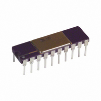
IC LVDT SIGNAL COND 20-CDIP
Manufacturer
Analog Devices Inc
Type
Signal Conditionerr
Specifications of AD598AD
Rohs Status
RoHS non-compliant
Input Type
Voltage
Output Type
Voltage
Interface
LVDT
Current - Supply
15mA
Mounting Type
Through Hole
Package / Case
20-CDIP (0.300", 7.62mm)
Bandwidth
20kHz
Supply Voltage Min
13V
Supply Voltage Max
36V
Digital Ic Case Style
DIP
No. Of Pins
20
Operating Temperature Range
-40°C To +85°C
Temperature Coefficient
250ppm/°C
Application
Proving ring-weigh scale, synchronous opeation of multiple LVDTS
Converter Type
voltage to Frequency
Current, Output
6 mA (Min.)
Impedance, Input
200 Kiloohms (Typ.)
Package Type
Ceramic DIP
Temperature, Operating, Maximum
85 °C
Temperature, Operating, Minimum
-40 °C
Voltage, Operating
36 V (Max.)
Lead Free Status / RoHS Status
Contains lead / RoHS non-compliant
Available stocks
Company
Part Number
Manufacturer
Quantity
Price

Part Number:
AD598AD
Manufacturer:
ADI/亚德诺
Quantity:
20 000


OPERATION WITH A HALF-BRIDGE TRANSDUCER
Although the AD598 is not intended for use with a half-bridge
type transducer, it may be made to function with degraded
performance.
A half-bridge type transducer is a popular transducer. It works
in a similar manner to the LVDT in that two coils are wound
around a moveable core and the inductance of each coil is a
function of core position.
In the circuit shown in Figure 27 the V
are developed as two resistive-inductor dividers. If the inductors
are equal (i.e., the core is centered), the V
ages to the AD598 are equal and the output voltage V
zero. When the core is positioned off center, the inductors are
unequal and an output voltage V
The linearity of this circuit is dependent upon the value of the
resistors in the resistive-inductor dividers. The optimum value
may be transducer dependent and therefore must be selected by
REV. A
SANGAMO
AGHI
HALF-BRIDGE
MECHANICAL
POSITION
INPUT
SANGAMO
AGHI
HALF-BRIDGE
MECHANICAL
POSITION
INPUT
300
1 F
OUT
1 F
is developed.
300
A
1 F
500
500
and V
A
and V
Figure 28. Alternate Half-Bridge Circuit
B
input voltages
Figure 27. Half-Bridge Operation
B
input volt-
4nF
OUT
4nF
1.87k
0.1 F
0.1 F
is
– V
– V
5k
10
2
3
4
5
6
7
8
9
10
0.1 F
1
–15–
8
1
2
3
4
5
6
7
9
0.1 F
LEV 2
–V
EXC 1
EXC 2
LEV 1
FREQ 1
FREQ 2
B1 FILT
B2 FILT
V
LEV 2
EXC 1
EXC 2
LEV 1
FREQ 1
FREQ 2
B1 FILT
B2 FILT
–V
V
B
B
S
S
trial and error. The 300
nonlinearity of the transfer function to within several tenths of
1%. This circuit uses a Sangamo AGH1 half-bridge transducer.
The 1 F capacitor blocks the dc offset of the excitation output
signal. The 4 nF capacitor sets the transducer excitation fre-
quency to 10 kHz as recommended by the manufacturer.
ALTERNATE HALF-BRIDGE TRANSDUCER CIRCUIT
This circuit suffers from similar accuracy problems to those
mentioned in the previous circuit description. In this circuit the
V
of core position, and the input signal V
tation voltage level. However, a nonlinearity is introduced by
the A–B/A+B transfer function.
The 500
caused by dc bias currents from the V
in the previous circuit these bias currents see very low resistance
paths to ground through the coils.
A
AD598
AD598
input signal to the AD598 really and truly is a linear function
FEEDBACK
FEEDBACK
OFFSET 2
OFFSET 1
OUT FILT
OFFSET 2
OFFSET 1
SIG OUT
OUT FILT
SIG REF
SIG OUT
A1 FILT
A2 FILT
SIG REF
A1 FILT
A2 FILT
resistors in this circuit are chosen to minimize errors
+V
+V
V
0.1 F
V
A
S
0.1 F
A
S
16
13
12
20
19
18
17
15
14
11
20
19
18
17
16
15
14
13
12
11
+ V
+ V
143k
82.5k
0.33 F
0.1 F
0.33 F
0.1 F
resistors in this circuit optimize the
FULL SCALE
V
V
FULL SCALE
OUT
A
OUT
B
and V
, is one half of the exci-
10V
10V
B
inputs. Note that
AD598
Related parts for AD598AD
Image
Part Number
Description
Manufacturer
Datasheet
Request
R

Part Number:
Description:
±1.7g Dual-Axis IMEMS Accelerometer Evaluation Board
Manufacturer:
Analog Devices Inc
Datasheet:

Part Number:
Description:
Inertial Sensor Evaluation System
Manufacturer:
Analog Devices Inc
Datasheet:
Part Number:
Description:
Manufacturer:
Analog Devices Inc
Datasheet:
Part Number:
Description:
Manufacturer:
Analog Devices Inc
Datasheet:
Part Number:
Description:
Manufacturer:
Analog Devices Inc
Datasheet:
Part Number:
Description:
Manufacturer:
Analog Devices Inc
Datasheet:
Part Number:
Description:
Manufacturer:
Analog Devices Inc
Datasheet:
Part Number:
Description:
Manufacturer:
Analog Devices Inc
Datasheet:
Part Number:
Description:
Manufacturer:
Analog Devices Inc
Datasheet:
Part Number:
Description:
Manufacturer:
Analog Devices Inc
Datasheet:
Part Number:
Description:
Manufacturer:
Analog Devices Inc
Datasheet:
Part Number:
Description:
Manufacturer:
Analog Devices Inc
Datasheet:
Part Number:
Description:
Manufacturer:
Analog Devices Inc
Datasheet: