786554-1 TE Connectivity, 786554-1 Datasheet

786554-1

Manufacturer Part Number
786554-1
Description
Manufacturer
TE Connectivity
Datasheets

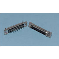
Specifications of 786554-1

Product Type
Connector
Pcb Mounting Orientation
Vertical
Termination Method To Pc Board
Through Hole - Solder
Pcb Mount Retention
With
Pcb Mount Alignment
Without
Shell Type
Full Metal
Product Series
Series III
Shell Material
Carbon Steel
Bracket Material
Zinc
Mating Retention Type
Latching
Bracket Plating
Nickel over Copper
Shielded
Yes
Termination Post Length (mm [in])
4.39 [0.173]
Number Of Positions
20
Pcb Mount Retention Type
ACTION PIN (Compliant) Posts
Mating Retention
With
Centerline (mm [in])
1.27 [0.050]
Post Plating
Tin Lead over Nickel
Shell Plating
Tin over Copper
Contact Plating, Mating Area, Material
Gold (30)
Contact Base Material
Phosphor Bronze
Connector Style
Receptacle
Mating Alignment
With
Mating Alignment Type
Rails
Housing Material
Thermoplastic - GF
Ul Flammability Rating
UL 94V-0
Housing Color
Black
Rohs/elv Compliance
RoHS compliant, ELV compliant
Lead Free Solder Processes
Not relevant for lead free process
Rohs/elv Compliance History
Always was RoHS compliant
Pcb Thickness, Recommended (mm [in])
1.57 – 2.36 [0.062 – 0.093]

Available stocks

Company
Part Number
Manufacturer
Quantity
Price
Part Number:
786554-1
Manufacturer:
TE Connectivity AMP Connectors
Quantity:
457
1.
1.1.
1.2.
2.
3.
3.1.
3.2.
3.3.
©2011 Tyco Electronics Corporation,
a TE Connectivity Ltd. Company
All Rights Reserved
TE logo is a trademark.
SCOPE
Content
This specification covers perform ance, tests and quality requirem ents for AMPLIMITE* .050 series
product. This product consists of printed circuit board m ounted and cable applied plug and receptacle
connectors, excluding S-Bus, ACTION PIN* connectors and product intended for term ination to .025
inch centerline ribbon cable and surface m ount product.
Qualification
W hen tests are perform ed on subject product line, procedures specified in Figure 1 shall be used. All
inspections shall be perform ed using the applicable inspection plan and product drawing.
APPLICABLE DOCUM ENTS
The following TE Connectivity (TE) docum ents form a part of this specification to the extent specified
herein. Unless otherwise specified, the latest edition of the docum ent applies. In the event of conflict
between the requirem ents of this specification and the product drawing, the product drawing shall take
precedence. In the event of conflict between the requirem ents of this specification and the referenced
docum ents, this specification shall take precedence.
!
!
!
!
REQUIREM ENTS
Design and Construction
Product shall be of the design, construction and physical dim ensions specified on the applicable product
drawing.
Materials
Materials used in the construction of this product shall be as specified on the applicable product
drawing.
Ratings
!
!
!
109-1: Test Specification (General Requirem ents for Test Specifications)
109 Series: Test Specifications as indicated in Figure 1
114-40029: Application Specification (AMPLIMITE* .050 Series Insulation Displacem ent and
Printed Circuit Board Connectors)
501-155: Qualification Test Report (Connector, AMPLIMITE*, Shielded, .050)
Voltage: 30 volts AC per UL and CSA
Current: Signal application only, 1 am pere m axim um at 50% energized, See Figure 2.
Tem perature: -55 to 105°C
| Indicates change
*Trademark
Product
Specification
Connector, AMPLIMITE*, Shielded, .050 Series
For latest revision, visit our website at www.te.com/documents.
For Regional Customer Service, visit our website at www.te.com
Other products, logos, and company names might be trademarks of their respective owners.
108-1228
11Mar11 Rev F
1 of 7
LOC B

Related parts for 786554-1

786554-1 Summary of contents

Page 1

... APPLICABLE DOCUM ENTS The following TE Connectivity (TE) docum ents form a part of this specification to the extent specified herein. Unless otherwise specified, the latest edition of the docum ent applies. In the event of conflict between the requirem ents of this specification and the product drawing, the product drawing shall take precedence ...

Page 2

Perform ance and Test Description Product is designed to m eet the electrical, m echanical and environm ental perform ance requirem ents specified in Figure 1. Unless otherwise specified, all tests shall be perform bient environm ...

Page 3

Test Description Mating force. Unm ating force. Housing lock strength. Therm al shock. Hum idity-tem perature cycling. Tem perature life. Mixed flowing gas. Shall meet visual requirements, show no physical damage and shall meet requirements of NOTE additional tests as ...

Page 4

Product Qualification and Requalification Test Sequence Test or Exam ination Exam ination of product Term ination resistance Insulation resistance Dielectric withstanding voltage Capacitance Vibration Physical shock Durability Mating force Unm ating force Housing lock strength Therm al shock Hum ...

Page 5

QUALITY ASSURANCE PROVISIONS 4.1. Qualification Testing A. Sam ple Selection Sam ples shall be prepared in accordance with applicable Instruction Sheets and shall be selected at random from current production. All test groups shall consist of num ber of ...

Page 6

Quality Conform ance Inspection The applicable quality inspection plan will specify the sam pling acceptable quality level to be used. Dim ensional and functional requirem ents shall be in accordance with the applicable product drawing and this specification. 4.5. ...

Page 7

Right Angle Boardm ount Receptacle/Cable Plug Panel Mount Receptacle/Cable Plug Vertical Boardm ount Vibration & Physical Shock Mounting & Clam ping Location Vibration & Physical Shock Mounting & Clam ping Location Rev F Figure 6 Figure 7 108-1228 7 of ...

Related keywords