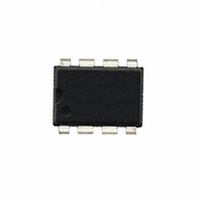
604-00038 Parallax Inc, 604-00038 Datasheet - Page 6

604-00038
Manufacturer Part Number
604-00038
Description
IC SENSOR TOUCH/PROXMTY 1CH 8DIP
Manufacturer
Parallax Inc
Series
QProx™r
Type
Capacitiver
Datasheet
1.604-00038.pdf
(12 pages)
Specifications of 604-00038
Touch Panel Interface
1, 2-Wire
Number Of Inputs/keys
1 Key
Resolution (bits)
14 b
Data Interface
Serial
Voltage Reference
Internal
Voltage - Supply
2.5 V ~ 5.5 V
Current - Supply
1.5mA
Operating Temperature
0°C ~ 70°C
Mounting Type
Through Hole
Package / Case
8-DIP (0.300", 7.62mm)
Output Type
Logic
Input Type
Logic
Product
Microcontroller Accessories
Lead Free Status / RoHS Status
Lead free / RoHS Compliant
Interface
-
Lead Free Status / RoHS Status
Lead free / RoHS Compliant, Lead free / RoHS Compliant
Electromechanical devices like relays will usually ignore this
short pulse. The pulse also has too low a duty cycle to visibly
affect LED’s. It can be filtered completely if desired, by
adding an RC timeconstant to filter the output, or if interfacing
directly and only to a high-impedance CMOS input, by doing
nothing or at most adding a small non-critical capacitor from
Out to ground (Figure 2-5).
The QT113H variant has an active-high output; the heartbeat
signal of the QT113H works in exactly the same manner.
2.2.4 O
The QT113’s `output is active low and can sink up to 5mA of
non-inductive current. If an inductive load is used, such as a
small relay, the load should be diode clamped to prevent
damage. When set to operate in a proximity mode (at high
gain) the current should be limited to 1mA to prevent gain
shifting side effects from occurring, which happens when the
load current creates voltage drops on the die and bonding
wires; these small shifts can materially influence the signal
level to cause detection instability as described below.
Care should be taken when the QT113 and the load are both
powered from the same supply, and the supply is minimally
regulated. The QT113 derives its internal references from the
power supply, and sensitivity shifts can occur with changes in
Vdd, as happens when loads are switched on. This can
induce detection ‘cycling’, whereby an object is detected, the
load is turned on, the supply sags, the detection is no longer
sensed, the load is turned off, the supply rises and the object
is reacquired, ad infinitum. To prevent this occurrence, the
output should only be lightly loaded if the device is operated
from an unregulated supply, e.g. batteries. Detection
Getting HearBeat pulses with a pull-down resistor
H eartBeat™ P ulses
UTPUT
C M O S
Figure 2-5 Eliminating HB Pulses
MIC RO INPU T
G ATE OR
D
R o
RIVE
100p F
2
3
4
Figure 2-3
O UT
O PT 1
O PT 2
C
+2 .5 to 5
o
1
8
V dd
V ss
2
3
4
S NS 2
GAIN
S NS 1
O UT
O PT1
O PT2
7
5
6
SN S 2
GA IN
SN S 1
7
5
6
Microcontroller
- 6 -
Using a micro to obtain HB pulses in either output state
‘stiction’, the opposite effect, can occur if a load is shed when
Out is active.
The output of the QT113 can directly drive a resistively
limited LED. The LED should be connected with its cathode
to the output and its anode towards Vcc, so that it lights when
the sensor is active. If desired the LED can be connected
from Out to ground, and driven on when the sensor is
inactive.
The QT113H variant has an active-high output.
3 - CIRCUIT GUIDELINES
3.1 SAMPLE CAPACITOR
Charge sampler Cs can be virtually any plastic film or
medium-K ceramic capacitor. The acceptable Cs range is
from 10nF to 500nF depending on the sensitivity required;
larger values of Cs demand higher stability to ensure reliable
sensing. Acceptable capacitor types include polycarbonate,
PPS film, or NPO/C0G ceramic.
3.2 OPTION STRAPPING
The option pins Opt1 and Opt2 should never be left floating.
If they are floated, the device will draw excess power and the
options will not be properly read on powerup. Intentionally,
there are no pullup resistors on these lines, since pullup
resistors add to power drain if tied low.
The Gain input should be connected to either Vdd or Gnd.
Tables 1-1 and 2-1 show the option strap configurations
available.
3.4 POWER SUPPLY, PCB LAYOUT
The power supply can range from 2.5 to 5.0 volts. At 3 volts
current drain averages less than 600µA in most cases, but
can be higher if Cs is large. Increasing Cx values will actually
decrease power drain. Operation can be from batteries, but
be cautious about loads causing supply droop (see Output
Drive, previous section).
As battery voltage sags with use or fluctuates slowly with
temperature, the QT113 will track and compensate for these
changes automatically with only minor changes in sensitivity.
If the power supply is shared with another electronic system,
care should be taken to assure that the supply is free of
PORT_M.x
PORT_M.y
Figure 2-4
R
o
2
3
4
OUT
OPT1
OPT2
SNS2
GAIN
SNS1
7
5
6


