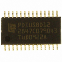
PDIUSBD12PWTM ST-Ericsson Inc, PDIUSBD12PWTM Datasheet - Page 21

PDIUSBD12PWTM
Manufacturer Part Number
PDIUSBD12PWTM
Description
IC USB INTRFC W/PARL BUS 28TSSOP
Manufacturer
ST-Ericsson Inc
Datasheet
1.PDIUSBD12PWTM.pdf
(40 pages)
Specifications of PDIUSBD12PWTM
Applications
USB Host/Peripheral Controller
Interface
Parallel
Voltage - Supply
3 V ~ 3.6 V, 4 V ~ 5.5 V
Package / Case
28-TSSOP
Mounting Type
Surface Mount
For Use With
D12 ISA PC EVAL KIT - EVAL KIT FOR PDIUSBD12 USB EPP
Lead Free Status / RoHS Status
Lead free / RoHS Compliant
Other names
568-1092-2
PDIUSBD12PW,118
PDIUSBD12PWDH-T
PDIUSBD12PW,118
PDIUSBD12PWDH-T
Available stocks
Company
Part Number
Manufacturer
Quantity
Price
Company:
Part Number:
PDIUSBD12PWTM
Manufacturer:
ST
Quantity:
4 500
Philips Semiconductors
PDIUSBD12_9
Product data sheet
11.3.5 Read Buffer
11.3.6 Write Buffer
11.3.7 Clear Buffer
Code (Hex) — F0
Transaction — read multiple bytes (max. 130)
The Read Buffer command is followed by a number of data reads that return contents of
the selected endpoint data buffer. After each read, the internal buffer pointer is
incremented by 1.
The buffer pointer is reset to the top of the buffer by the Read Buffer command. This
means that reading or writing a buffer can be interrupted by any other command (except
for Select Endpoint).
The data in the buffer is organized as follows:
The first two bytes will be skipped in the DMA read operation. Therefore, the first read will
get data byte 1, the second read will get data byte 2, and so on. The PDIUSBD12 can
determine the last byte of this packet through the EOP termination of the USB packet.
Code (Hex) — F0
Transaction — write multiple bytes (max. 130)
The Write Buffer command is followed by a number of data writes that load the endpoints
buffer. Data must be organized in the same way as described in the Read Buffer
command. The first byte (reserved) should always be 0.
During the DMA write operation, the first two bytes will be bypassed. Therefore, the first
write will write into data byte 1, the second write will write into data byte 2, and so on. For
non-isochronous transfer (bulk or interrupt), the buffer must be completely filled before
data is sent to the host and a switch to the next buffer occurs. The exception is at the end
of the DMA transfer indicated by activation of EOT_N, when the current buffer content
(completely full or not) will be sent to the host.
Remark: There is no protection against writing or reading over a buffer’s boundary, or
against writing into an OUT buffer or reading from an IN buffer. Any of these actions could
cause an incorrect operation. Data in an OUT buffer is only meaningful after a successful
transaction. The exception is during the DMA operation on the main endpoint
(endpoint 2), in which case the pointer is automatically pointed to the second buffer after
reaching the boundary (double buffering scheme).
Code (Hex) — F2
Transaction — none
•
•
•
•
•
Byte 0: reserved; can have any value
Byte 1: number or length of data bytes
Byte 2: data byte 1
Byte 3: data byte 2
and so on
Rev. 09 — 11 May 2006
USB peripheral controller with parallel bus
© Koninklijke Philips Electronics N.V. 2006. All rights reserved.
PDIUSBD12
20 of 39


