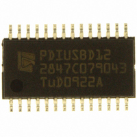
PDIUSBD12PWTM ST-Ericsson Inc, PDIUSBD12PWTM Datasheet - Page 38

PDIUSBD12PWTM
Manufacturer Part Number
PDIUSBD12PWTM
Description
IC USB INTRFC W/PARL BUS 28TSSOP
Manufacturer
ST-Ericsson Inc
Datasheet
1.PDIUSBD12PWTM.pdf
(40 pages)
Specifications of PDIUSBD12PWTM
Applications
USB Host/Peripheral Controller
Interface
Parallel
Voltage - Supply
3 V ~ 3.6 V, 4 V ~ 5.5 V
Package / Case
28-TSSOP
Mounting Type
Surface Mount
For Use With
D12 ISA PC EVAL KIT - EVAL KIT FOR PDIUSBD12 USB EPP
Lead Free Status / RoHS Status
Lead free / RoHS Compliant
Other names
568-1092-2
PDIUSBD12PW,118
PDIUSBD12PWDH-T
PDIUSBD12PW,118
PDIUSBD12PWDH-T
Available stocks
Company
Part Number
Manufacturer
Quantity
Price
Company:
Part Number:
PDIUSBD12PWTM
Manufacturer:
ST
Quantity:
4 500
Philips Semiconductors
24. Tables
Table 1.
Table 2.
Table 3.
Table 4.
Table 5.
Table 6.
Table 7.
Table 8.
Table 9.
Table 10. Error codes . . . . . . . . . . . . . . . . . . . . . . . . . . .19
Table 11. Interrupt modes . . . . . . . . . . . . . . . . . . . . . . . .22
Table 12. Limiting values . . . . . . . . . . . . . . . . . . . . . . . . .23
Table 13. Recommended operating conditions . . . . . . . .23
Table 14. Static characteristics (digital pins) . . . . . . . . . .23
Table 15. Static characteristics (AI/O pins) . . . . . . . . . . .24
Table 16. Dynamic characteristics (AI/O pins;
Table 17. Dynamic characteristics (parallel interface) . . .25
Table 18. Dynamic characteristics (DMA) . . . . . . . . . . . .27
Table 19. Suitability of surface mount IC packages for wave
Table 20. Abbreviations . . . . . . . . . . . . . . . . . . . . . . . . . .34
Table 21. Revision history . . . . . . . . . . . . . . . . . . . . . . . .35
PDIUSBD12_9
Product data sheet
Ordering information . . . . . . . . . . . . . . . . . . . . .2
Pin description . . . . . . . . . . . . . . . . . . . . . . . . . .4
Endpoint configuration . . . . . . . . . . . . . . . . . . .10
Command summary . . . . . . . . . . . . . . . . . . . .11
Set Mode command, configuration byte: bit
allocation . . . . . . . . . . . . . . . . . . . . . . . . . . . . .14
Set Mode command, clock division factor byte: bit
allocation . . . . . . . . . . . . . . . . . . . . . . . . . . . . .15
Set DMA command: bit allocation . . . . . . . . . .16
Read Interrupt register, byte 1: bit allocation . .17
Read Last Transaction Status register: bit
allocation . . . . . . . . . . . . . . . . . . . . . . . . . . . . .19
full-speed) . . . . . . . . . . . . . . . . . . . . . . . . . . . .24
and reflow soldering methods . . . . . . . . . . . . .33
Rev. 09 — 11 May 2006
USB peripheral controller with parallel bus
© Koninklijke Philips Electronics N.V. 2006. All rights reserved.
PDIUSBD12
continued >>
37 of 39


