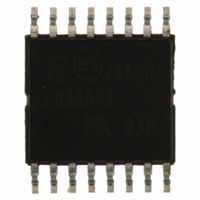
PM8800ATR STMicroelectronics, PM8800ATR Datasheet - Page 18

PM8800ATR
Manufacturer Part Number
PM8800ATR
Description
IC POE-PD PWM CTLR 16-HTSSOP
Manufacturer
STMicroelectronics
Datasheet
1.PM8800ATR.pdf
(35 pages)
Specifications of PM8800ATR
Applications
Power Over Ethernet (PoE)
Interface
IEEE 802.3af
Voltage - Supply
10 V
Package / Case
16-TSSOP Exposed Pad, 16-eTSSOP, 16-HTSSOP
Mounting Type
Surface Mount
For Use With
497-6366 - BOARD EVAL FOR PM8800A
Lead Free Status / RoHS Status
Lead free / RoHS Compliant
Other names
497-6897-2
PM8800ATR
PM8800ATR
Available stocks
Company
Part Number
Manufacturer
Quantity
Price
Company:
Part Number:
PM8800ATR
Manufacturer:
ON
Quantity:
300 000
Part Number:
PM8800ATR
Manufacturer:
ST
Quantity:
20 000
PD interface
5.3
5.4
18/35
Table 7.
Under voltage lock-out
After the classification is completed, the PSE raises the voltage to provide the Power
Devices with the negotiated power. During the transition from low to operating voltage, the
internal UVLO is released and the hot-swap MOSFET is activated initiating the in-rush
sequence.
The IEEE 802.3af standard sets a maximum turn-on voltage (42 V) and the minimum turn-
off voltage (30 V) for the PDs and indicates normal voltage drops across the Ethernet cable.
The PM8800A implements the UVLO mechanism by setting 2 internal thresholds on the
voltage across the VIN-VSS pins; one is to activate the hot-swap (V
is to switch off the hot-swap MOSFET upon detection of a supply voltage drop (V
from normal operating conditions.
No additional external components are required to comply with the IEEE 802.3af
requirements. Thermal protection alarm overrides the gate driving of the MOSFET
immediately switching off the MOSFET itself in case of device overheating. The hot-swap is
bypassed also in auxiliary source topology supplying directly the PWM and not requiring the
hot-swap to be active.
In rush current limit
Once the detection and classification phases have been successfully completed, the PSE
raises the voltage across the Ethernet cable. When the voltage difference between the VIN
and VSS is greater than the V
on and the DC-DC input capacitance is charged in a controlled way.
As depicted in the following figure, the current delivered by the hot-swap MOSFET during
inrush period is a function of the voltage drop between GND and VSS (hot-swap drain
source terminals). In more detail, the higher the voltage across the internal hot-swap, the
lower the current flowing trough it, so that the total dissipated power is almost constant
throughout the inrush phase, preventing the IC to reach the thermal protection limit.
The lower current limitation is internally set at 140 mA and takes action when the voltage
GND-VSS is above 30 V. The second limit is set at 250 mA when GND-VSS voltage is
between 30 V and 15 V. When the voltage falls below 15 V, the limit switches to the higher
CLASS
0
1
2
3
4
value of the external classification resistor for the different PD class of
power
PD power (W)
0.44 - 12.95
6.49 - 12.95
0.44 - 3.84
3.84 - 6.49
Reserved
UVLO_R
threshold, the internal hot-swap MOSFET is switched
R
CLASS
Open
82.5
52.3
36.5
158
(Ω)
Classification current (mA)
min
17
26
36
0
9
UVLO_R
IEEE 802.3af
), while the other
UVLO_F
max
PM8800A
12
20
30
44
4
)


