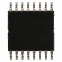
PM8800ATR STMicroelectronics, PM8800ATR Datasheet - Page 21

PM8800ATR
Manufacturer Part Number
PM8800ATR
Description
IC POE-PD PWM CTLR 16-HTSSOP
Manufacturer
STMicroelectronics
Datasheet
1.PM8800ATR.pdf
(35 pages)
Specifications of PM8800ATR
Applications
Power Over Ethernet (PoE)
Interface
IEEE 802.3af
Voltage - Supply
10 V
Package / Case
16-TSSOP Exposed Pad, 16-eTSSOP, 16-HTSSOP
Mounting Type
Surface Mount
For Use With
497-6366 - BOARD EVAL FOR PM8800A
Lead Free Status / RoHS Status
Lead free / RoHS Compliant
Other names
497-6897-2
PM8800ATR
PM8800ATR
Available stocks
Company
Part Number
Manufacturer
Quantity
Price
Company:
Part Number:
PM8800ATR
Manufacturer:
ON
Quantity:
300 000
Part Number:
PM8800ATR
Manufacturer:
ST
Quantity:
20 000
PM8800A
5.6
Figure 12. DC current vs R
This limitation is active after nPGD set and when the PD is supplied through the PoE or in
the Front connection (see
The PM8800A useful programming range for the current limitation is between 150 mA and
800 mA. Practical resistor value ranges between 15 kΩ and 75 kΩ.
HV regulator startup
PM8800A embeds a high voltage start-up regulator to provide a controlled reference voltage
of 8.3 V to the Current mode PWM during its start-up phase.
The regulator output is connected to the VCC pin as well as to the DC DC section
In normal isolated topology, the VCC pin is diode connected to the auxiliary winding of the
transformer used for the flyback or forward configuration. When the voltage from the
transformer exceeds the regulated voltage, the high voltage regulator is shut off, reducing
the amount of power dissipated inside the PM8800A.
The external auxiliary voltage must higher then 8.3 V but must be also lower than 15 V
under all working conditions, to avoid the intervent of the internal protection clamp.
A VCC UVLO mechanism monitors the level of voltage on the VCC pin. When VCC voltage
exceeds the VCC
VCC voltage drops under its VCC
900
800
700
600
500
400
300
200
100
0
10
UVLO_R
20
the PWM controller is enabled and it remains enabled until the
Section
DC
30
UVLO_F
7)
value.
40
R
DC
[kohm]
50
60
70
PD interface
80
21/35


