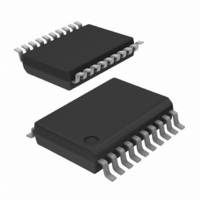
TJA1080ATS/2/T,112 NXP Semiconductors, TJA1080ATS/2/T,112 Datasheet - Page 14

TJA1080ATS/2/T,112
Manufacturer Part Number
TJA1080ATS/2/T,112
Description
IC TXRX FLEXRAY 20-SSOP
Manufacturer
NXP Semiconductors
Datasheet
1.TJA1080ATS2T118.pdf
(49 pages)
Specifications of TJA1080ATS/2/T,112
Applications
Automotive
Interface
Bus
Voltage - Supply
4.75 V ~ 5.25 V
Package / Case
20-SSOP
Mounting Type
Surface Mount
Lead Free Status / RoHS Status
Lead free / RoHS Compliant
Other names
935288151112
NXP Semiconductors
TJA1080A
Product data sheet
6.2.1 Normal mode
6.2.2 Receive-only mode
6.2.3 Standby mode
6.2.4 Go-to-sleep mode
In Normal mode the transceiver is able to transmit and receive data via the bus lines BP
and BM. The output of the normal receiver is directly connected to pin RXD.
The transmitter behavior in Normal mode of operation, with no time-out present on pins
TXEN and BGE and the temperature flag not set, is given in
In this mode pins INH1 and INH2 are set HIGH.
Table 8.
In Receive-only mode the transceiver can only receive data. The transmitter is disabled,
regardless of the voltages on pins BGE and TXEN.
In this mode pins INH1 and INH2 are set HIGH.
In Standby mode the transceiver has entered a low power mode which means very low
current consumption. In the Standby mode the device is not able to transmit or receive
data and the low power receiver is activated to monitor for bus wake-up patterns.
Standby mode can be entered if the correct polarity is applied to pins EN and STBN (see
Figure 5
In this mode, pin INH1 is set HIGH.
If the wake flag is set, pin INH2 is set to HIGH and pins RXEN and RXD are set to LOW,
otherwise pin INH2 is floating and pins RXEN and RXD are set to HIGH; see
In this mode the transceiver behaves as in Standby mode. If this mode is selected for a
longer time than the go-to-sleep hold time parameter (minimum hold time) and the wake
flag has been previously cleared, the transceiver will enter Sleep mode, regardless of the
voltage on pin EN.
BGE
L
X
H
H
TXEN
X
H
L
L
and
Transmitter function table
Table
All information provided in this document is subject to legal disclaimers.
TXD
X
X
H
L
4) or an undervoltage is present on pin V
Rev. 5 — 24 February 2011
Transmitter
transmitter is disabled
transmitter is disabled
transmitter is enabled; the bus lines are actively driven; BP is driven
HIGH and BM is driven LOW
transmitter is enabled; the bus lines are actively driven; BP is driven
LOW and BM is driven HIGH
CC
Table
; see
8.
TJA1080A
FlexRay transceiver
Figure
© NXP B.V. 2011. All rights reserved.
5.
Section
14 of 49
6.5.


