ZMOT0BSB0C0AG Zilog, ZMOT0BSB0C0AG Datasheet - Page 56
ZMOT0BSB0C0AG
Manufacturer Part Number
ZMOT0BSB0C0AG
Description
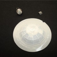
Processors - Application Specialized ZMB Nic RE200B-P Pyr Fr CM 0.77 GI V5 Len
Manufacturer
Zilog
Datasheet
1.ZMOT0BSB0A0AG.pdf
(65 pages)
Specifications of ZMOT0BSB0C0AG
Operating Supply Voltage
2.7 V to 3.6 V
Maximum Operating Temperature
+ 105 C
Mounting Style
SMD/SMT
Package / Case
SOIC-8
Core
Z8FS040
Number Of Timers
2
Processor Series
ZMOTION
Program Memory Size
4 KB
Program Memory Type
Flash
Lead Free Status / Rohs Status
Details
Available stocks
Company
Part Number
Manufacturer
Quantity
Price
Company:

Part Number:
ZMOT0BSB0C0AG
Manufacturer:
Zilog
Quantity:
3


Appendix B. PIR Engine Initialization and
Control
PS028511-0112
The application software must execute an initialization procedure to enable the PIR
engine. Once the PIR engine is enabled, it runs in the background from the ADC interrupt.
Every ADC conversion generates an interrupt and the PIR engine performs its functions
during this time. The user application code runs in the foreground and monitors the status
through the API and performs any other functions required for the application.
The PIR engine also requires a one-second tick to perform several housekeeping opera-
tions and to keep track of its sampling rate. This tick must be provided by the user applica-
tion through the Status/Control Register 1 (Engine Timer Tick). Once per second, this bit
should be set to a 1 by the application software to provide the engine with a 1-second time
base. The accuracy of this time is not critical, but should be within +/– 10%.
There are two basic modes in which the PIR engine operates: NORMAL SCAN RATE
Mode and LOW SCAN RATE Mode. See the description of the PIR Scan Rate bit in the
PIR Status/Control Register 1 for more details.
The PIR engine runs in the background from the ADC interrupt (initiated by the applica-
tion). Engine processing is done during the ADC interrupt. Therefore CPU loading is
based on the sample rate of the ADC. To ensure a consistent sample rate, the Engine must
know the MCU operating frequency (System Clock Frequency). It uses the Flash Fre-
quency Control Registers to determine the operating frequency which must be initialized
prior to starting the Engine.
The Flash Frequency High (FFREQH) and Flash Frequency Low Byte (FFREQL) regis-
ters combine to form a 16-bit value FFREQ primarily to control timing for Flash program
and erase functions. This value is also used by the PIR software engine to calculate the
required sample rate of the ADC and other functions. The 16-bit value for FFREQ is the
System Clock Frequency in KHz and is calculated using the following equation.
FFREQ[15:0] = {FFREQH[7:0],FFREQL[7:0]} = (System Clock
Frequency)/1000
Observe the following procedure to initialize the PIR engine – a process that is common to
both the Normal Scan Rate and Low Scan Rate modes:
1. Set up the API control registers (standard and advanced).
2. Initialize the FFREQH and FFREQL registers with the MCU clock frequency.
3. Write the PIR Enable Pattern to the PIR Enable Register.
4. Call PIR Init.
ZMOTION™ Detection and Control Family
PIR Engine Initialization and Control
Product Specification
49
Related parts for ZMOT0BSB0C0AG
Image
Part Number
Description
Manufacturer
Datasheet
Request
R

Part Number:
Description:
Communication Controllers, ZILOG INTELLIGENT PERIPHERAL CONTROLLER (ZIP)
Manufacturer:
Zilog, Inc.
Datasheet:

Part Number:
Description:
KIT DEV FOR Z8 ENCORE 16K TO 64K
Manufacturer:
Zilog
Datasheet:

Part Number:
Description:
KIT DEV Z8 ENCORE XP 28-PIN
Manufacturer:
Zilog
Datasheet:

Part Number:
Description:
DEV KIT FOR Z8 ENCORE 8K/4K
Manufacturer:
Zilog
Datasheet:

Part Number:
Description:
KIT DEV Z8 ENCORE XP 28-PIN
Manufacturer:
Zilog
Datasheet:

Part Number:
Description:
DEV KIT FOR Z8 ENCORE 4K TO 8K
Manufacturer:
Zilog
Datasheet:
Part Number:
Description:
CMOS Z8 microcontroller. ROM 16 Kbytes, RAM 256 bytes, speed 16 MHz, 32 lines I/O, 3.0V to 5.5V
Manufacturer:
Zilog, Inc.
Datasheet:
Part Number:
Description:
Low-cost microcontroller. 512 bytes ROM, 61 bytes RAM, 8 MHz
Manufacturer:
Zilog, Inc.
Datasheet:
Part Number:
Description:
Z8 4K OTP Microcontroller
Manufacturer:
Zilog, Inc.
Datasheet:
Part Number:
Description:
CMOS SUPER8 ROMLESS MCU
Manufacturer:
Zilog, Inc.
Datasheet:
Part Number:
Description:
SL1866 CMOSZ8 OTP Microcontroller
Manufacturer:
Zilog, Inc.
Datasheet:
Part Number:
Description:
SL1866 CMOSZ8 OTP Microcontroller
Manufacturer:
Zilog, Inc.
Datasheet:
Part Number:
Description:
OTP (KB) = 1, RAM = 125, Speed = 12, I/O = 14, 8-bit Timers = 2, Comm Interfaces Other Features = Por, LV Protect, Voltage = 4.5-5.5V
Manufacturer:
Zilog, Inc.
Datasheet:
Part Number:
Description:
Manufacturer:
Zilog, Inc.
Datasheet: