ZMOT0BSB1A0AG Zilog, ZMOT0BSB1A0AG Datasheet - Page 33
ZMOT0BSB1A0AG
Manufacturer Part Number
ZMOT0BSB1A0AG
Description
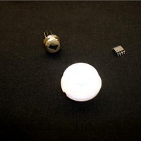
Processors - Application Specialized ZMB Nic RE200B-P Pyr Nic. NCL-9(26) Lens
Manufacturer
Zilog
Datasheet
1.ZMOT0BSB0A0AG.pdf
(65 pages)
Specifications of ZMOT0BSB1A0AG
Operating Supply Voltage
2.7 V to 3.6 V
Maximum Operating Temperature
+ 105 C
Mounting Style
SMD/SMT
Package / Case
SOIC-8
Core
Z8FS040
Number Of Timers
2
Processor Series
ZMOTION
Program Memory Size
4 KB
Program Memory Type
Flash
Lead Free Status / Rohs Status
Details
Available stocks
Company
Part Number
Manufacturer
Quantity
Price
Company:

Part Number:
ZMOT0BSB1A0AG
Manufacturer:
Zilog
Quantity:
3


PS028511-0112
Frequency Response (Bits 6–3)
PIR Scan Rate (Bit 2)
Frequency Response of PIR engine; controlled by Application
Range: 0h–Ch
• This value determines the frequency response of the motion detection system. Higher values allow
• The frequency of the signal that is presented to the PIR engine is largely dependent on the structure
Note: Lower programmed values also have the effect of reducing the relative range of detection.
PIR ADC conversion rate for the Pyroelectric Sensor; controlled by the application.
• The PIR engine performs the necessary ADC conversions on the PIR sensor input. Each conversion
• In NORMAL SCAN RATE Mode (PIR Scan Rate set to 0), the Z8FS040 ADC peripheral is set to
• When LOW SCAN RATE Mode is selected by setting this bit to a 1, CONTINUOUS CONVERSION
• In LOW SCAN RATE Mode, the ADC is disabled between conversions to reduce power consumption.
• Although the LOW SCAN RATE Mode provides the application with more processing power and the
• If the PIR Scan Rate bit is changed during engine operation, the engine will stop detecting motion for
lower frequencies to be accepted by the PIR engine. Lower values cause the Engine to ignore targets
that generate lower frequencies. These targets typically include horizontally oriented objects such as
pets.
of the PIR lens being used (number and dispersion of beams). A lens with several evenly distributed
beams provides better frequency response performance than a lens with an uneven beam
distribution.
generates an interrupt that is processed by the PIR engine from the EPIR_ADC_ISR macro. The PIR
Scan Rate bit determines the rate at which the ADC conversions are generated.
CONTINUOUS CONVERSION Mode, which causes a conversion to be carried out automatically
every 256 system clocks. In this mode, the application is only required to execute the EPIR_ADC_ISR
macro for each ADC interrupt. The ADC continually runs and continuously generates interrupts.
Mode is disabled and the ADC is operated in SINGLE-SHOT Mode such that each conversion takes
5129 system clocks to complete. In this mode, the application software must initiate the ADC
conversion request (set bit 7 of ADCCTL0) and execute the EPIR_ADC_ISR macro once every 5mS.
Power consumption can be reduced further if the application software uses this mode in conjunction
with the CPU’s Halt or Stop modes. Alternately, this mode can be used to provide the application
software with additional CPU processing time.
opportunity for the system to reduce power consumption, the normal scan rate will provide better
sensitivity and range. While operating in LOW SCAN RATE Mode, sensitivity is reduced by
approximately 20%. The performance of Direction Detection may also be reduced in this mode. EMC
immunity is disabled while in LOW SCAN RATE Mode.
up to 200mS to avoid potential false motion detection. When changing the PIR SCAN RATE Mode,
the Advanced API registers must first be updated with the appropriate values.
0 = NORMAL SCAN RATE Mode
1 = LOW SCAN RATE Mode
ZMOTION™ Detection and Control Family
Product Specification
Standard API Register Set
26
Related parts for ZMOT0BSB1A0AG
Image
Part Number
Description
Manufacturer
Datasheet
Request
R

Part Number:
Description:
Communication Controllers, ZILOG INTELLIGENT PERIPHERAL CONTROLLER (ZIP)
Manufacturer:
Zilog, Inc.
Datasheet:

Part Number:
Description:
KIT DEV FOR Z8 ENCORE 16K TO 64K
Manufacturer:
Zilog
Datasheet:

Part Number:
Description:
KIT DEV Z8 ENCORE XP 28-PIN
Manufacturer:
Zilog
Datasheet:

Part Number:
Description:
DEV KIT FOR Z8 ENCORE 8K/4K
Manufacturer:
Zilog
Datasheet:

Part Number:
Description:
KIT DEV Z8 ENCORE XP 28-PIN
Manufacturer:
Zilog
Datasheet:

Part Number:
Description:
DEV KIT FOR Z8 ENCORE 4K TO 8K
Manufacturer:
Zilog
Datasheet:
Part Number:
Description:
CMOS Z8 microcontroller. ROM 16 Kbytes, RAM 256 bytes, speed 16 MHz, 32 lines I/O, 3.0V to 5.5V
Manufacturer:
Zilog, Inc.
Datasheet:
Part Number:
Description:
Low-cost microcontroller. 512 bytes ROM, 61 bytes RAM, 8 MHz
Manufacturer:
Zilog, Inc.
Datasheet:
Part Number:
Description:
Z8 4K OTP Microcontroller
Manufacturer:
Zilog, Inc.
Datasheet:
Part Number:
Description:
CMOS SUPER8 ROMLESS MCU
Manufacturer:
Zilog, Inc.
Datasheet:
Part Number:
Description:
SL1866 CMOSZ8 OTP Microcontroller
Manufacturer:
Zilog, Inc.
Datasheet:
Part Number:
Description:
SL1866 CMOSZ8 OTP Microcontroller
Manufacturer:
Zilog, Inc.
Datasheet:
Part Number:
Description:
OTP (KB) = 1, RAM = 125, Speed = 12, I/O = 14, 8-bit Timers = 2, Comm Interfaces Other Features = Por, LV Protect, Voltage = 4.5-5.5V
Manufacturer:
Zilog, Inc.
Datasheet:
Part Number:
Description:
Manufacturer:
Zilog, Inc.
Datasheet: