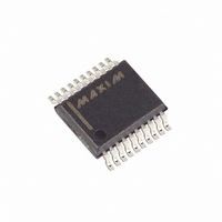
MAX4598EAP+ Maxim Integrated Products, MAX4598EAP+ Datasheet - Page 7

MAX4598EAP+
Manufacturer Part Number
MAX4598EAP+
Description
IC MULTIPLEXER DUAL 4X1 20SSOP
Manufacturer
Maxim Integrated Products
Datasheet
1.MAX4598EAP.pdf
(12 pages)
Specifications of MAX4598EAP+
Function
Multiplexer
Circuit
2 x 4:1
On-state Resistance
75 Ohm
Voltage Supply Source
Single, Dual Supply
Voltage - Supply, Single/dual (±)
2.7 V ~ 12 V, ± 2.7 V ~ 6 V
Operating Temperature
-40°C ~ 85°C
Mounting Type
Surface Mount
Package / Case
20-SSOP
Lead Free Status / RoHS Status
Lead free / RoHS Compliant
(T
A
PIN
10
11
12
13
14
15
16
17
18
19
20
= +25°C, unless otherwise noted.)
1
2
3
4
5
6
7
8
9
NLATCH
LATCH
NAME
COMB
COMA
GND
NO4
NO2
NO3
NO1
NO5
NO7
NO6
NO8
V+
EN
A1
A0
A3
A2
V-
-10
-20
-30
-40
-50
-70
-80
-90
-60
_______________________________________________________________________________________
0
Low-Voltage, Combination Single-Ended
0.1
Multiplexer Output B
Address Bit 1
Address Bit 0
Channel Input 4
Channel Input 2
Channel Input 3
Channel Input 1
Negative Supply Voltage
Positive Supply Voltage
Multiplexer Output A
Data-Strobe Mode Select
Latch Input
Multiplexer Enable
Channel Input 5
Channel Input 7
Channel Input 6
Channel Input 8
Address Bit 3
Address Bit 2
Ground
INSERTION LOSS
ON-PHASE
FREQUENCY RESPONSE
1
OFF-ISOLATION
8-to-1/Differential 4-to-1 Multiplexer
FREQUENCY (MHz)
Pin Description
FUNCTION
10
100
Typical Operating Characteristics (continued)
MAX4598-09
1000
140
100
60
20
-20
-100
-140
180
-60
-180
The MAX4598 can be configured as a single 8-channel
or dual 4-channel multiplexer. In the single 8-to-1 multi-
plexer configuration, COMA connects to one of the
eight inputs (NO1 to NO8), GND, or V+ by the address
inputs A0 to A2 (see Truth Table ). In the dual 4-to-1
multiplexer configuration, COMA connects to one of the
four inputs (NO1, NO3, NO5, NO7), GND, or V+, and
COMB connects to one of the four inputs (NO2, NO4,
NO6, NO8) or GND by the address inputs A0 to A2
(see Truth Table ).
The MAX4598 functions as a standard multiplexer
when NLATCH is high. When NLATCH is low, the con-
dition set by A0 to A3 is activated at the rising edge of
LATCH. Otherwise, the outputs remain at the previously
set condition.
The MAX4598 construction is typical of most CMOS
analog switches. It has three supply pins: V+, V-, and
GND. The positive and negative power supplies are
used to drive the internal CMOS switches and set the
limits of the analog voltage on any switch. Reverse
ESD-protection diodes are internally connected be-
tween each analog signal pin and V+ and V-. If the volt-
age on any pin exceeds V+ or V- by 0.3V, one of the
ESD diodes starts to conduct. During normal operation
these reverse-biased ESD diodes leak, forming the only
current drawn from V-.
_______________Detailed Description
__________Applications Information
-1
-2
6
5
4
3
2
1
0
-5
-4 -3
CHARGE INJECTION vs. V
-2
-1
V+ = +5V
V- = -5V
V
COM
0
(V)
1
V+ = +5V
V- = 0
2
COM
3
4
5
7


