DM330012 Microchip Technology, DM330012 Datasheet - Page 16
DM330012
Manufacturer Part Number
DM330012
Description
55T2293
Manufacturer
Microchip Technology
Datasheet
1.DM330012.pdf
(30 pages)
Specifications of DM330012
Core Architecture
DsPIC
Core Sub-architecture
DsPIC33
Silicon Core Number
DsPIC33E
Kit Contents
DsPIC33E Or PIC24E USB Starter Kit Board, USB Cable
Available stocks
Company
Part Number
Manufacturer
Quantity
Price
Company:

Part Number:
DM330012
Manufacturer:
MICROCHIP
Quantity:
12 000


2.2
DS51936B-page 16
FEATURES
This section describes the key features of the starter kit. Refer to
Figure 1-2
2.2.1
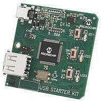
The dsPIC33E USB Starter Kit is designed with a permanently mounted (i.e., soldered)
dsPIC33EP512MU810 DSC. Similarly, the PIC24E USB Starter Kit is designed with a
permanently mounted (i.e., soldered) PIC24EP512GU810 MCU.
2.2.2
There are two ways to supply power to the dsPIC33E or PIC24E USB Starter Kit:
• Connect the USB Debug connector J2 to a PC running MPLAB using the supplied
• An external application board with a regulated DC power supply that provides +5V
One green LED (D4) is provided to show that the dsPIC33E or PIC24E device is being
powered.
2.2.3
The dsPIC33E or PIC24E USB Starter Kit includes a PIC24FJ256GB106 USB micro-
controller that provides debugger connectivity over USB. The PIC24FJ256GB106 is
hard-wired to the dsPIC33E or PIC24E device to translate the I/O pins of the
PIC24FJ256GB106 device to the ICSP™ pins of the dsPIC33E or PIC24E device. The
debugger circuit also includes a 25LC256 Serial EEPROM device for data storage.
The programming/debugging circuit on the dsPIC33E or PIC24E USB Starter Kit is similar
in functionality and feature-set to the MPLAB PICkit™ 3 debugger.
2.2.4
There are three possible ways to connect to the dsPIC33E or PIC24E USB
microcontroller:
• Host mode
• Device mode
mini-B to full-sized A cable
can be connected to the application board connector (J3) that is provided on the
bottom side of the board
Connect the device to the type-A connector J6, located on the top side of the
starter kit. If using the debug USB port to power the Host port, install jumper J5 to
short the back-power prevention diode. Note that a maximum of ~400 mA can be
supplied from the debug USB port to the host port using this method. If the full
500 mA supply is needed for the application, an external supply must be
connected to the application board and jumper J5 must be removed to prevent
back-powering the debug USB port.
First, connect the debug mini-B USB cable to port J2. Next, connect the starter kit
to the USB Host using a cable with a type-B micro plug to the starter kit’s micro-B
port J4, located on the bottom side of the starter kit. The other end of the cable
must have a type-A plug. Connect it to a USB host. Jumper J5 should be
removed.
Processor Support
Power Supply
Debug USB Connectivity
dsPIC33E/PIC24E USB Connectivity
in
Chapter 1. “Introduction”
for their actual locations on the board.
© 2010-2011 Microchip Technology Inc.
Figure 1-1
and
Related parts for DM330012
Image
Part Number
Description
Manufacturer
Datasheet
Request
R

Part Number:
Description:
Manufacturer:
Microchip Technology Inc.
Datasheet:
Part Number:
Description:
Manufacturer:
Microchip Technology Inc.
Datasheet:
Part Number:
Description:
Manufacturer:
Microchip Technology Inc.
Datasheet:
Part Number:
Description:
Manufacturer:
Microchip Technology Inc.
Datasheet:
Part Number:
Description:
Manufacturer:
Microchip Technology Inc.
Datasheet:
Part Number:
Description:
Manufacturer:
Microchip Technology Inc.
Datasheet:
Part Number:
Description:
Manufacturer:
Microchip Technology Inc.
Datasheet:
Part Number:
Description:
Manufacturer:
Microchip Technology Inc.
Datasheet: